Working method of waste material clearing device

A technology for cleaning devices and working methods, applied to auxiliary devices, manufacturing tools, metal processing equipment, etc., can solve the problems of affecting the processing quality of the next workpiece, inconvenient cleaning of waste materials, etc., and achieve lower temperature, simple structure, easy to place and take take advantage of convenience

Inactive Publication Date: 2018-05-08
朱慧
View PDF4 Cites 3 Cited by
  • Summary
  • Abstract
  • Description
  • Claims
  • Application Information

AI Technical Summary

Problems solved by technology

[0004] For this reason, the technical problem to be solved by the present invention is that waste material occurs after laser cutting in the prior art, because the laser cutting temperature is higher, the waste material temperature is also higher, it is inconvenient to clean up the waste material, and the waste material is easy to affect the next generation after accumulation. The processing quality of the workpiece, thus proposing a working method of a waste cleaning device for laser cutting equipment

Method used


Image

  • Working method of waste material clearing device
  • Working method of waste material clearing device
  • Working method of waste material clearing device

Examples


Embodiment Construction

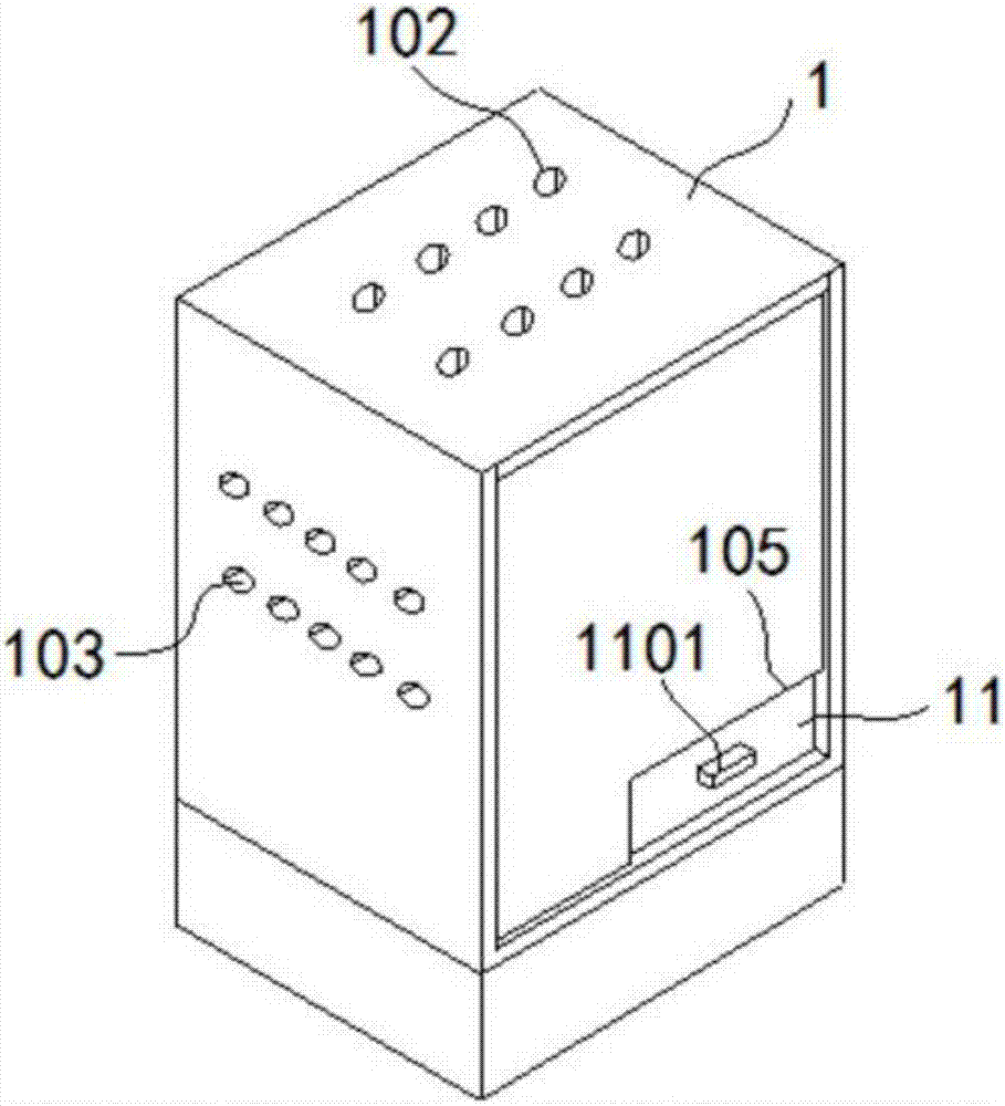
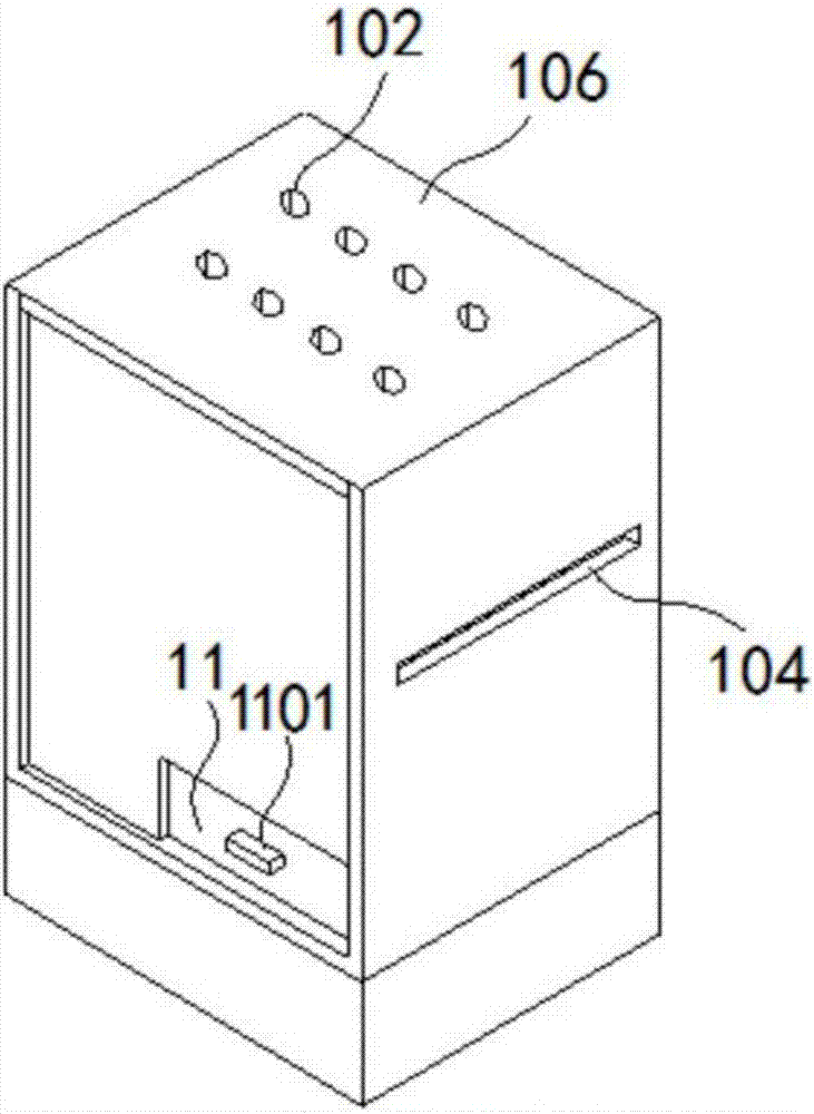
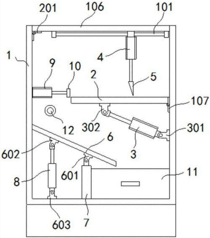
[0028] Such as figure 1 , figure 2 , image 3 As shown, the waste cleaning device for laser cutting equipment of the present invention includes:

[0029] A protective box 1, the protective box 1 is installed on the bracket, the top of the protective box 1 is provided with a sliding device 101, the inner side wall of the protective box 1 is provided with a long groove 104, the protective box A notch 105 is formed on the front side wall of the body 1 . The upper cover of the protective box 1 is provided with several air inlet holes 102 , and the side wall of the protective box 1 is provided with several air outlet holes 103 . The upper cover 106 of the protective box 1 is a reversible structure, and the upper cover 106 is hinged on an inner side wall of the protective box 1 through a second hinge 107 .

[0030] Processing platform 2, the processing platform 2 is arranged in the protective box 1, one side of the processing platform 2 is hinged on the inner side wall of the p...


PUM


Abstract

The invention discloses a working method of a waste material clearing device. The waste material clearing device comprises a protecting box body, a machining platform, a discharging air cylinder, a first lifting air cylinder, a scraper, a flow guide plate, a supporting rod, a second lifting air cylinder, a material pushing air cylinder, a pushing plate and a water material box. The discharging aircylinder is arranged below the machining platform, pouring of waste materials can be achieved, the waste materials are guided into the waste material box through the flow guide plate, the waste materials obtained after laser cutting can be cleared in time, and the influence on machining quality of laser cutting of the next time is prevented. By arranging the material pushing air cylinder, the pushing plate and a long groove in the side wall, machined products can be pushed out of the protecting box body conveniently, products to be machined are placed into the long groove, and the machining efficiency is improved. By arranging the first lifting air cylinder and the scraper, the waste materials remaining on the machining platform can be further cleared, and the machining quality is furtherimproved. The protecting box body is provided with a wind input hole and a wind output hole, the temperature in the protecting box body is lowered, and the machining quality is ensured.

Description

technical field [0001] The invention belongs to the technical field of laser cutting, and in particular relates to a working method of a waste material cleaning device used in laser cutting equipment. Background technique [0002] Laser cutting is the use of high-power-density laser beams to irradiate materials, so that the materials are quickly heated to the vaporization temperature, and evaporate to form holes. As the beam moves to the material, the holes continuously form narrow (such as about 0.1mm) slits, and the process is completed. Cutting of material. Laser cutting is one of the thermal cutting methods. Laser cutting can be divided into four categories: laser vaporization cutting, laser melting cutting, laser oxygen cutting, and laser scribing and controlled fracture. It has the advantages of good cutting quality, high cutting efficiency, and fast cutting speed. It is a commonly used thermal cutting method for some sheet metal parts. [0003] However, the existin...

Claims


Application Information

Patent Timeline
Patent Type & Authority Applications(China)
IPC IPC(8): B23K26/16B23K26/70B23K26/38
CPCB23K26/16B23K26/38B23K26/702B23K37/00B23K37/08
Inventor 不公告发明人
Owner 朱慧
Why Eureka
Try Eureka