
Efficient punching machine for packaging bag

A technology of punching machine and packaging bag, applied in metal processing and other directions, can solve the problems of packaging punching that cannot have a special shape, the accuracy of punching position is not high, and can only be operated on a plane, so as to improve punching efficiency and reduce Worker's workload, the effect of improving efficiency

Active Publication Date: 2018-05-08
重庆帅业电力机械有限公司
View PDF4 Cites 0 Cited by
  • Summary
  • Abstract
  • Description
  • Claims
  • Application Information

AI Technical Summary

Problems solved by technology

[0002] There will be a round hole on the packaging bag of the product, especially for small products, so that the product can be hung on the shelf after entering the mall or store for customers to choose. The general packaging production equipment does not have the function of opening the hole and requires manual labor. In the later stage, the surface of the packaging bag will be opened with a special opening device. Due to the error of manual operation, the accuracy of the opening position is not high, and it can only be operated on a plane, and it is impossible to open holes in an oblique direction for some special-shaped packages.

Method used


Image

  • Efficient punching machine for packaging bag
  • Efficient punching machine for packaging bag
  • Efficient punching machine for packaging bag

Examples


Embodiment Construction

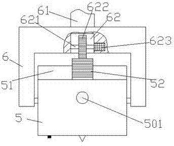
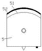
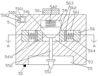
[0020] Such as Figure 1-Figure 5 As shown, a high-efficiency packaging bag punching machine of the present invention includes a bracket 6 and a punching machine 5 that is rotatably mounted in the bracket 6, and the top of the punching machine 5 is provided with a transition section 51. A toothed arc bar 52 is fixed on the transition section 51, and an angle adjustment device cooperating with the toothed arc bar 52 is provided in the bracket 6 on the upper side of the toothed arc bar 52. A first accommodation groove 55 is provided, and the inside of the drilling machine 5 on the upper side of the first accommodation groove 55 is provided with a first sliding cavity 53 extending left and right, and the middle part of the inner top wall of the first sliding cavity 53 is connected. A second sliding chamber 54 is provided, and a pushing block 541 is slidingly fitted and connected in the second sliding chamber 54, and a first compression spring 542 is arranged in the second sliding...


PUM


Abstract

The invention discloses an efficient punching machine for a packaging bag. The punching machine comprises a support and a punching machine body which is rotationally installed in the support in a matched mode; a transition section is arranged at the top part of the punching machine body, and a tooth arc strip is fixedly arranged on the transition section; an angle adjusting device which is connected with the tooth arc strip in a matched mode is arranged in the support on the upper side of the tooth arc strip; a first containing groove is formed in the bottom surface of the hole opening machinebody, wherein a first sliding cavity extending leftwards and rightwards is formed in the part, on the upper side of the first containing groove, of the punching machine, and a second sliding cavity is formed in the middle part of the top wall in the first sliding cavity in a penetrating mode; a pushing block is connected in the second sliding cavity in a sliding fit mode, and a first pressing spring is arranged in the position, at the top part of the pushing block, of the second sliding cavity; the bottom part of the pushing block is fixedly provided with a protruding block which extends intothe first sliding cavity; and a push column extending leftwards and rightwards is slidably connected to the position, between the bottom part of the first sliding cavity and the top part of the firstcontaining groove, of the interior of the punching machine. The punching machine has the advantages of being simple in structure, convenient to operate and capable of improving the working efficiencyand quality of punching.

Description

technical field [0001] The invention relates to the technical field of packaging bag opening, in particular to an efficient packaging bag opening machine. Background technique [0002] There will be a round hole on the packaging bag of the product, especially for small products, so that the product can be hung on the shelf after entering the mall or store for customers to choose. The general packaging production equipment does not have the function of opening the hole and requires manual labor. In the later stage, the surface of the packaging bag is drilled with a special punching device. Due to the error of manual operation, the accuracy of the punching position is not high, and it can only be operated on a plane, and it is impossible to punch holes in an oblique direction for some special-shaped packages. Contents of the invention [0003] The technical problem to be solved by the present invention is to provide an efficient packaging bag opening machine, which can solve...

Claims


Application Information

Patent Timeline
IPC IPC(8): B26F1/00B26D7/26B26D5/16
CPCB26D5/16B26D7/2628B26F1/00
Inventor 江桂荣
Owner 重庆帅业电力机械有限公司
Learn More