Multi-layer coextrusion device and application method thereof

A multi-layer co-extrusion and insulating layer technology, which is applied to other home appliances, applications, coatings, etc., can solve the problems of inaccurate positioning, easy contamination, mismatching, etc., and achieve a fixed and tight effect

Active Publication Date: 2018-05-08
ANHUI HUANRUI ELECTROTHERMAL EQUIP
View PDF8 Cites 9 Cited by
  • Summary
  • Abstract
  • Description
  • Claims
  • Application Information

AI Technical Summary

Problems solved by technology

The disadvantage of this process is that if a compact compression mold is used when wrapping the compound multiple times, the inner mold is easy to scratch the first layer of cladding, and because each layer of cladding is easily polluted due to multiple wrapping, and the positioning It is not allowed to be easily eccentric; if the extrusion die is used, it mainly depends on the characteristics of the material of the wrapping itself to achieve a good fixation between the wrapping, the metal inner core, and the PTC inner core. Short circuit and mismatch occur after using for a long time

Method used


Image

  • Multi-layer coextrusion device and application method thereof
  • Multi-layer coextrusion device and application method thereof
  • Multi-layer coextrusion device and application method thereof

Examples


Embodiment 1

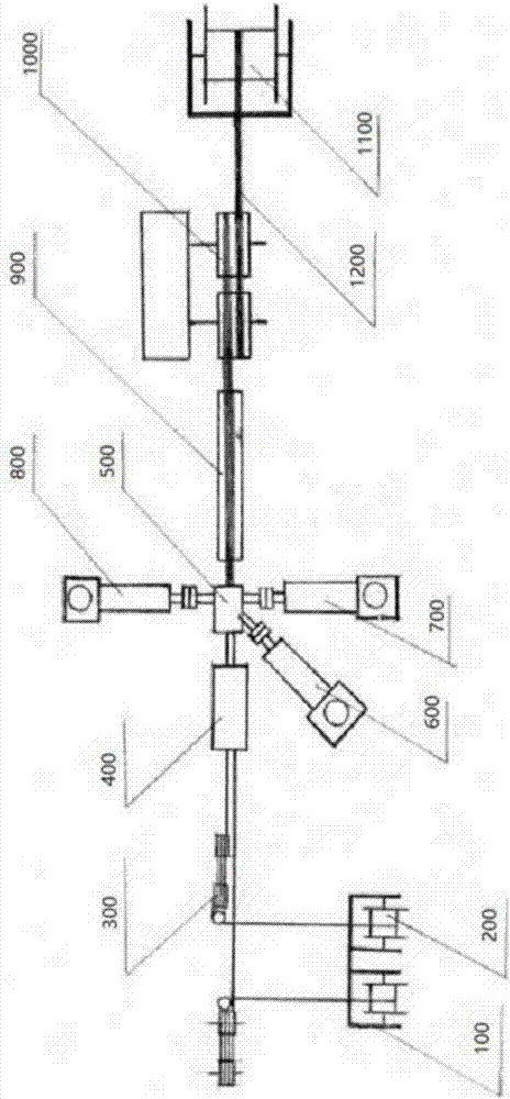
[0033] Such as figure 1 As shown, figure 1 It is a schematic diagram of the overall structure of the present invention. The multi-layer co-extrusion device includes an active pay-off machine, a pay-off reel, a dance wheel, a heater, a co-extrusion head, a plastic extruder, a constant temperature water tank, a traction device, and a take-up reel . Two metal cores 1200 are actively released from the two active pay-off machines 100 and the two pay-off reels 200, and after being tensioned by the dance wheel 300 and heated by the heater 400, they enter the three The co-extrusion head 500 between the plastic extruders is coated with an inner conductor layer, a PTC heating element layer, and a composite insulating layer at a time, and then cooled by the constant temperature water tank 900, and then is cooled by the traction device 1000 and the take-up reel 1100 are closed. During the manufacturing process, the tension of the two metal cores 1200 should be kept consistent; the plastic...

Embodiment 2

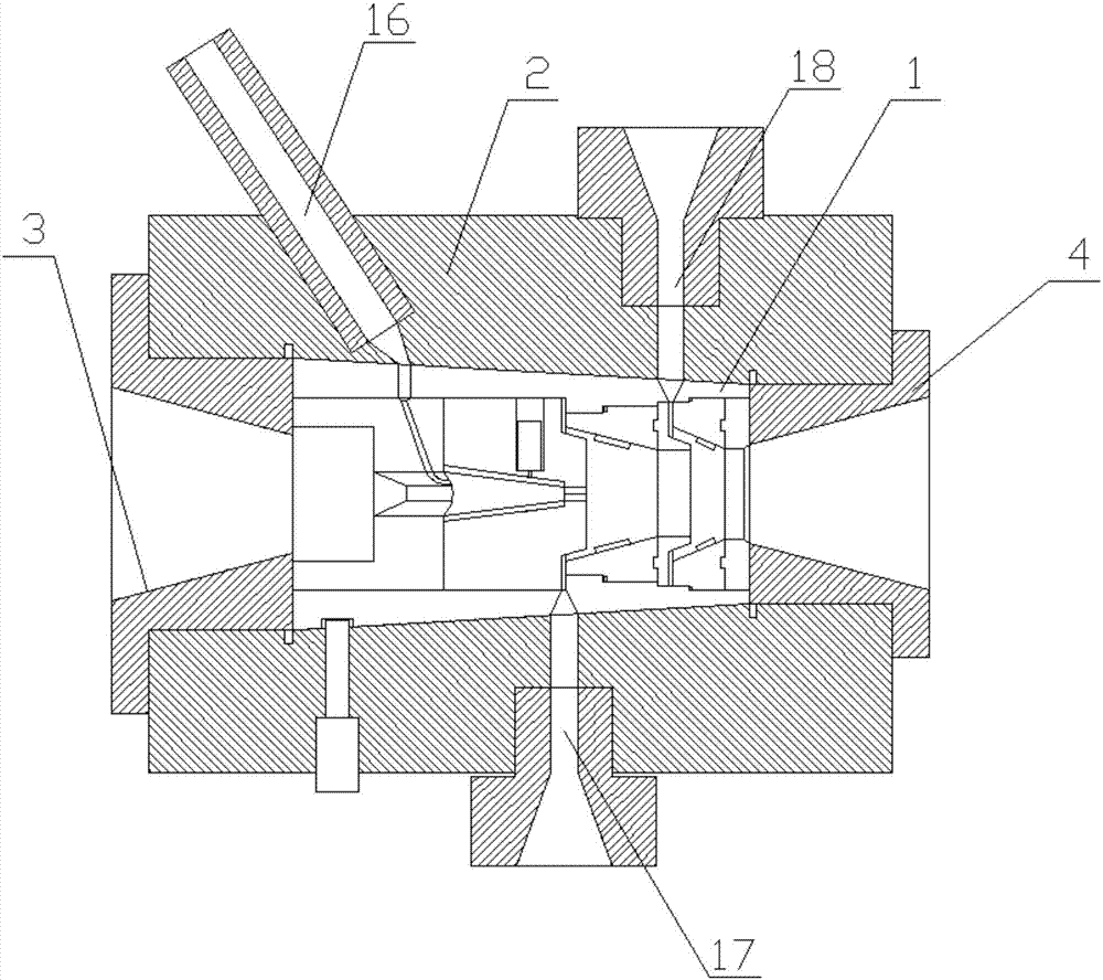
[0040] Such as image 3 As shown, image 3 It is a structural view (front view) of the composite module according to the present invention. The wire inlet positioning module 12 includes a wire inlet mold 121 and a positioning mold 122.

[0041] The wire inlet mold 121 is set at the feed end of the mold core support sleeve 11, and the wire inlet mold 121 is provided with a number of through holes according to the number of inner cores of the heating cable. In this embodiment, two are provided, and the positioning mold 122 is set In the through hole, the positioning mold 122 is preferably set as a cylinder, the positioning mold 122 is provided with a positioning hole, the metal core is set in the positioning hole, and the positioning mold 122 is connected to the entering hole. The wire mold 121 is fixedly connected by pins or bolts. The wire inlet positioning module 12 can be suitable for making different heating cables by replacing the positioning mold 122 with positioning holes of...

Embodiment 3

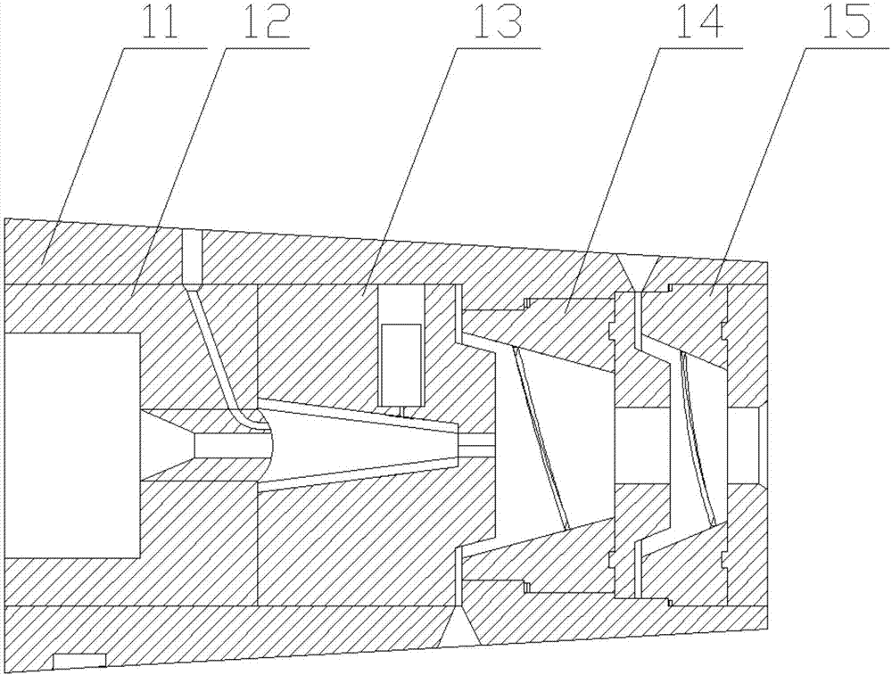
[0043] The third embodiment improves the inner conductor layer module. Specifically, the inner conductor layer module 13 includes a fixed mold 131 and a rotating mold 132.

[0044] Such as Figure 4 As shown, Figure 4 This is a structural view of the composite module (top view); the fixed mold 131 is fixed in the mold core support sleeve 11 by a fixed connection such as pins or bolts, and a number of through holes are arranged in the fixed mold 131 according to the number of through holes. A first molding cavity. The first molding cavity includes a rotating portion 133 and a molding portion 134. The rotating portion 133 is set in a conical shape. The rotating mold 132 is disposed in the rotating portion 133. The mold 132 can be freely rotated in the rotating part 133; the rotating mold 132 is a hollow cone-shaped tube structure, and the outer surface of the rotating mold 132 and the inner surface of the rotating part 133 are arranged in size matching to realize the rotating mold ...


PUM


Abstract

The invention discloses a multi-layer coextrusion device and an application method thereof. The multi-layer coextrusion device comprises a machine head, an active paying-off machine, a conductor paying-off disc, a dance wheel, a heater, a coextrusion machine head, a constant-temperature water tank, a traction device and a winding disc. The coextrusion machine head comprises a composite module, a shell, a front gland and a rear gland. The composite module comprises a die core supporting sleeve, a wire inlet positioning module, an inner conductor layer module, a PTC layer module and an insulation layer module. The PTC layer module comprises a PCT wrapping die and a sizing die. The position, at the PTC layer module, of the die core supporting sleeve is provided with a first annular boss. ThePCT wrapping die is provided with a first linkage part to be matched with the first annular boss, and the PCT wrapping die is in sliding connection with the sizing die. According to the multi-layer coextrusion device and the application method thereof, through the arrangement of a first gear set and a second gear set, reverse rotation of the PTC layer module and the insulation layer module is achieved, and fixation between a PTC heating body layer and a composite insulation layer is tighter.

Description

Technical field [0001] The invention relates to the field of wire and cable manufacturing equipment, in particular to a multi-layer co-extrusion device and a method of use thereof. Background technique [0002] For heating cables, three-layer co-extrusion devices have been commonly used in the domestic cable industry, and some domestic manufacturers also refer to imported three-layer co-extrusion devices for manufacturing. As for the dual-core double-layer structure ribbon cable commonly used in the fields of communications, petrochemicals and household appliances, imported and some domestic manufacturers mostly use the head of the ring-shaped feed channel three-layer co-extrusion device to manufacture, generally through The production process of layered multiple extrusion coatings first coat the two core structures with one layer of composite and then coat more than two layers of composite; for example, first coat a layer of coating on the conductor, and then The two wire cores...

Claims


Application Information

Patent Timeline
Patent Type & Authority Applications(China)
IPC IPC(8): B29C47/08B29C47/06B29C47/02B29C47/26B29L31/34B29C48/335
CPCB29C48/025B29C48/154B29C48/18B29C48/30B29C48/3366B29L2031/3462
Inventor 计成志
Owner ANHUI HUANRUI ELECTROTHERMAL EQUIP
Why Eureka
Try Eureka