Lining structure of rare earth electrolysis cell, and rare earth electrolysis cell

An electrolytic cell and lining technology, which is applied in the electrolytic process, electrolytic components, cells, etc., can solve the problems of unfavorable cathode and anode structures in the electrolysis process, large-scale electrolytic rare earths, no reduction in the voltage of the rare earth electrolytic cell, and the bottom of the electrolytic cell is easily corroded. , to achieve the effect of reasonable material selection and layout of lining structure, reasonable thermal insulation design and good thermal balance performance

Active Publication Date: 2018-05-08
CENT SOUTH UNIV
View PDF8 Cites 9 Cited by
  • Summary
  • Abstract
  • Description
  • Claims
  • Application Information

AI Technical Summary

Problems solved by technology

[0003] Chinese invention patent CN103614747A discloses a large-scale combined rare earth molten salt electrolytic cell system, which realizes a compact cell structure and a reasonable wiring structure. Voltage, and the design of the cathode and anode structure is not conducive to the operation of the electrolysis process and the enlargement of the electrolytic rare earth
[0004] Chinese invention patent CN105441987A discloses a rare earth molten salt electrolytic cell for producing rare earth metals and alloys with a liquid cathode. The structure is that the cathode and anode are inserted into the electrolyte in parallel and vertically. , but the liquid metal is used as the cathode, it is easy to cause secondary oxidation of the metal, and the liquid metal is always in the reaction zone, which makes the bottom of the electrolytic cell easy to be corroded, and at the same time brings great difficulties to the start-up operation of the electrolytic cell
In addition, liquid metal is used as the cathode, which increases the area of ​​the cathode and reduces the current density of the cathode, resulting in a decrease in current efficiency.

Method used


Image

  • Lining structure of rare earth electrolysis cell, and rare earth electrolysis cell
  • Lining structure of rare earth electrolysis cell, and rare earth electrolysis cell
  • Lining structure of rare earth electrolysis cell, and rare earth electrolysis cell

Examples


Embodiment Construction

[0042]The present invention will be described in detail below with reference to the accompanying drawings and examples. It should be noted that, in the case of no conflict, the embodiments of the present invention and the features in the embodiments can be combined with each other. For the convenience of description, if the words "up", "down", "left" and "right" appear in the following, it only means that the directions of up, down, left and right are consistent with the drawings themselves, and do not limit the structure.

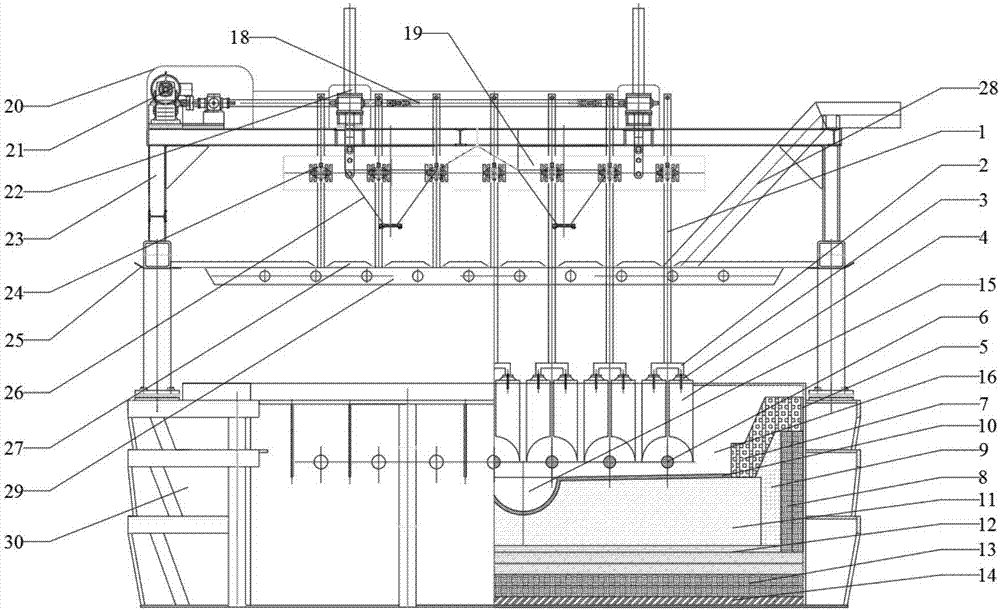
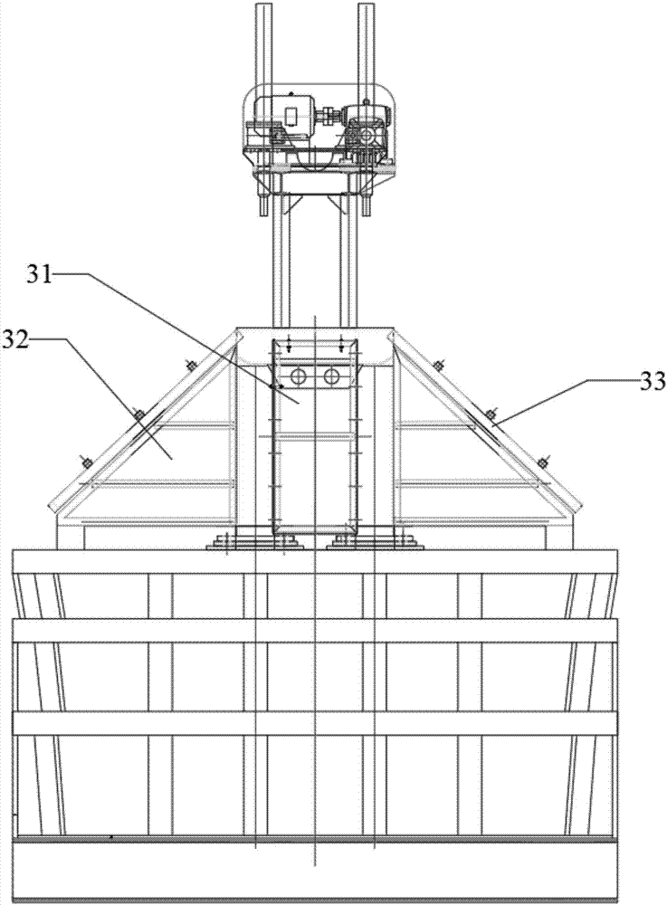
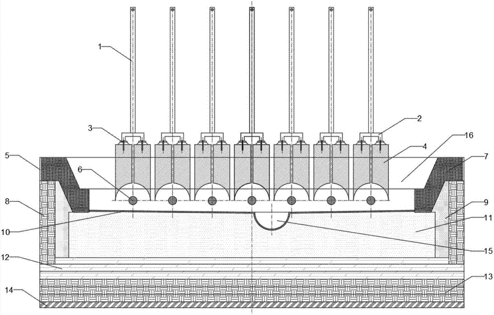
[0043] Such as Figure 1 to Figure 4 As shown, a rare earth electrolytic cell includes a cell upper structure, a cell shell 30, a bottom lining, a side lining, a cathode structure, and an anode structure. 23. A sealing system and other components, the anode lifting structure includes a lifting motor 21, a transmission guide rod 18, a lifting rod 22, a protective cover 20, a bus bar 19, a clamp 24, and a hook 25; the sealing system includes an end sealing ...


PUM

PropertyMeasurementUnit
thicknessaaaaaaaaaa
thicknessaaaaaaaaaa
thicknessaaaaaaaaaa

Abstract

The invention relates to a lining structure of a rare earth electrolysis cell, and the electrolysis cell. The lining structure comprises a bottom lining and a side lining, wherein the bottom lining comprises a ceramic fiber layer, a bottom refractory layer, an impermeable layer and a graphite layer which are sequentially stacked from bottom to top; the side lining is arranged in a manner of surrounding the bottom lining; the side lining extends upwards to achieve the space above the top surface of the graphite layer; and the bottom lining and the side lining are combined and encircled to forma cavity allowing an electrolysis reaction to be carried out. The lining structure of the rare earth electrolysis cell is reasonable in structural material selection and layout, and the electrolysis cell is high in heat balance performance, and capable of effectively reducing heat loss; a hearth of the electrolysis cell is easier to form due to the use of a silicon carbide protection layer with high heat conductivity, so that a side heat-insulation material of the electrolysis cell is much effectively protected; and in addition, a cylindrical cathode is adopted, so that the phenomenon that a current density is high at the cathode and low at an anode is more obvious, and an electrolysis reaction area is effectively enlarged.

Description

technical field [0001] The invention relates to a lining structure of a molten salt rare earth electrolytic cell and the rare earth electrolytic cell, belonging to the technical field of rare earth molten salt electrolytic equipment. Background technique [0002] The existing rare earth electrolysis mainly uses rare earth oxides as raw materials and fluorides as electrolytes for the molten salt rare earth electrolysis process. The electrolytic cell type is an up-plug cathode and anode structure. The cathode and anode cylinders are placed in the electrolyte in parallel, and a tungsten crucible is placed below. Used to receive metal. Most of the existing rare earth electrolyzers are open-top designs, and their thermal insulation is poor, and a large amount of heat is lost to the air through radiation and convection, thereby increasing the ambient temperature, deteriorating the working environment of workers, and making the electrolyzer The thermal balance of the electrolytic ...

Claims


Application Information

Patent Timeline
Patent Type & Authority Applications(China)
IPC IPC(8): C25C7/00C25C3/34
CPCC25C3/34C25C7/005
Inventor 吕晓军韩泽勋张恒星王维维苇茗仁孙启东
Owner CENT SOUTH UNIV
Why Eureka
Try Eureka