
Treatment method of anchor rope within the range of foundation pit envelop enclosure

A technology of foundation pit enclosure and treatment method, which is applied in the direction of foundation structure engineering, excavation, sheet pile wall, etc., can solve the problems that affect the construction quality of the enclosure structure, cannot guarantee the verticality of the hole, destroy the geological structure, etc., and shorten the construction period. The effect of construction period, ensuring safety and quality, and speeding up construction progress

Active Publication Date: 2018-05-08
CHINA RAILWAY 16 BUREAU GRP BEIJING METRO ENG CONSTR +2
View PDF8 Cites 3 Cited by
  • Summary
  • Abstract
  • Description
  • Claims
  • Application Information

AI Technical Summary

Problems solved by technology

[0004] The above-mentioned anchor cable processing method has the following problems: 1. To destroy the original building structure, the project volume is large and coordination is difficult; 2. The original geological structure is destroyed, causing large-scale collapse, and backfilling affects the construction quality of the enclosure structure; 3. Impact drilling The verticality of the hole cannot be guaranteed, and the efficiency is low
Therefore, there are still significant unmet construction needs for urban construction, and it is urgent to develop better anchor cable processing methods

Method used


Image

  • Treatment method of anchor rope within the range of foundation pit envelop enclosure
  • Treatment method of anchor rope within the range of foundation pit envelop enclosure
  • Treatment method of anchor rope within the range of foundation pit envelop enclosure

Examples


Embodiment 1

[0070] Example 1 Hydraulic grab loading and unloading system

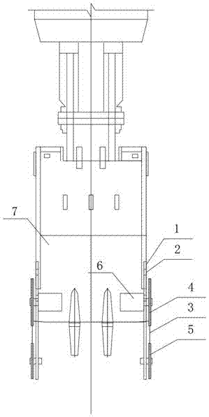
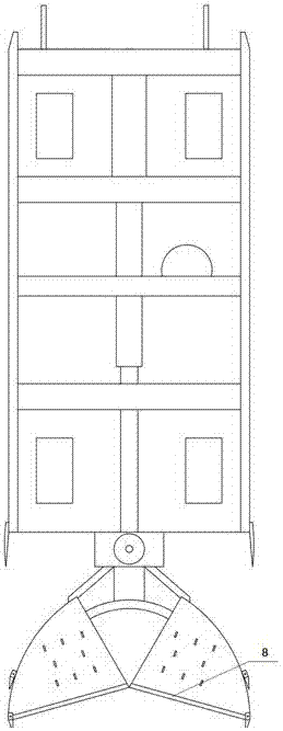
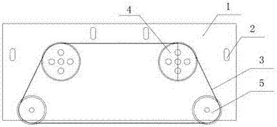
[0071] As attached to the manual Figure 1~6 As shown, the hydraulic grab loading and unloading system includes: a wire saw steel frame 1, a hydraulic grooving machine grab 7, and a wire saw. The wire saw includes: a wire saw chain 3 , a wire saw drive wheel 4 , a wire saw guide wheel 5 , and a wire saw hydraulic drive motor 6 .

[0072] Bolt holes are directly set on the wire saw steel plate frame 1 and the grab bucket 7 of the hydraulic grooving machine respectively. for circular holes. The wire saw steel frame 1 and the grab bucket 7 of the hydraulic grooving machine pass through the bolt holes and are connected with heavy-duty hexagonal bolts and nuts. The wire saw steel frame 1 is connected with the grab bucket 7 of the hydraulic grooving machine by bolts to realize fast disassembly and assembly.

[0073] The hydraulic grooving machine grab bucket 7 installs the wire saw at the wire saw installation posi...

Embodiment 2

[0075] Example 2 Hydraulic grab loading and unloading system

[0076] As attached to the manual Figure 1~6 As shown, the hydraulic grab loading and unloading system includes: a wire saw steel frame 1, a hydraulic grooving machine grab 7, and a wire saw. The wire saw includes: a wire saw chain 3 , a wire saw drive wheel 4 , a wire saw guide wheel 5 , and a wire saw hydraulic drive motor 6 .

[0077] Bolt holes are directly set on the wire saw steel plate frame 1 and the grab bucket 7 of the hydraulic grooving machine respectively. for circular holes. The wire saw steel plate frame 1 and the grab bucket 7 of the hydraulic grooving machine pass through the bolt holes and are connected with eyebolts and nuts.

[0078] The hydraulic grooving machine grab bucket 7 installs the wire saw at the wire saw installation position 8.

[0079] The connection mode of each component of the wire saw and the wire saw frame: the non-rotating part of the wire saw steel frame 1 and the wire ...

Embodiment 3

[0080] Example 3 Hydraulic grab loading and unloading system

[0081] As attached to the manual Figure 1~6 As shown, the hydraulic grab loading and unloading system includes: a wire saw steel frame 1, a hydraulic grooving machine grab 7, and a wire saw. The wire saw includes: a wire saw chain, a wire saw drive wheel 4, a wire saw guide wheel 5, a wire saw hydraulic drive motor 6, a wire saw steel plate frame 1 and a hydraulic grooving machine grab 7 are connected by bolts to realize fast disassembly and assembly. The hydraulic grooving machine grab bucket 7 installs the wire saw at the wire saw installation position 8.

[0082] Weld the connecting sheet with holes on the wire saw steel plate frame 1, and directly set the bolt holes on the grab bucket 7 of the hydraulic grooving machine. The hole on the connecting piece is an oval hole, and the bolt hole directly arranged on the grab bucket 7 of the hydraulic slotting machine is a circular hole. The wire saw steel plate f...


PUM


Abstract

The invention discloses a treatment method of an anchor rope within the range of a foundation pit envelop enclosure and belongs to the technical field of anchor rope treatment. According to the anchorrope treatment method disclosed by the invention, the construction scheme the grab bucket of a hydraulic trenching machine and a rope saw are adopted to cut off the anchor rope is adopted; before encountering the anchor rope, the hydraulic trenching machine is adopted for trenching operation; after encountering the anchor rope, a rope saw rack is detachably mounted on the grab bucket of the hydraulic trenching machine through a dismounting facility A; the grab bucket of the hydraulic trenching machine, the rope saw rack, the rope saw and the dismounting facility A jointly form a hydraulic grab bucket loading and unloading system; then, a hydraulic driving system of the hydraulic trenching machine is connected with a rope saw driving system; the hydraulic driving system of the hydraulic trenching machine drives the rope saw to cut the anchor rope; after the anchor rope is cut off, the hydraulic driving system of the hydraulic trenching machine is disconnected from the rope saw drivingsystem; the rope saw rack is dismantled; and the hydraulic trenching machine continuously carries out trenching operation. With adoption of the anchor rope treatment method, the anchor rope is cut offwhile trenching is carried out to realize the treatment purpose, the safety is high, the construction period is short, and the maneuverability is high.

Description

technical field [0001] The invention belongs to the technical field of anchor cable processing, and in particular relates to an anchor cable processing method within the scope of foundation pit enclosure protection structures. Background technique [0002] In the process of urban construction in our country, with the continuous increase of deep foundation pit projects, prestressed anchor cables have been widely used as an economical and effective means for the construction of civil foundation pit enclosure structures. Compared with other support technologies, the anchor cable has the advantages of low price, simple and mature construction, fast speed, safety and reliability, and does not occupy the main construction work. At the same time, as a temporary support measure, the anchor cable cannot be recycled after the support function fails, and is permanently buried underground together with the built structures and cannot be taken out, forming underground garbage, causing un...

Claims


Application Information

Patent Timeline
IPC IPC(8): E02D17/04E02D5/74
CPCE02D5/74E02D17/04
Inventor 张士强杨公正王起飞贺望宇陈桐民底龙飞李俊洋阮树林刘锐田文成程现伟王西林王波张南苗欲田周海松程鑫唐文周吴琼刘璞旭舒明江倪健付永阁李壮理
Owner CHINA RAILWAY 16 BUREAU GRP BEIJING METRO ENG CONSTR
Learn More