Light transmitting brick and preparation method thereof

A technology of light-transmitting bricks and bricks, which is applied in the field of optical fibers, can solve the problems that light-transmitting bricks are easily squeezed and deformed, optical fibers and bricks are easy to fall off or loosen, and achieve the effect of increasing strength and increasing friction

Pending Publication Date: 2018-05-08
CENTURY OPTICOMM CO LTD
View PDF0 Cites 1 Cited by
  • Summary
  • Abstract
  • Description
  • Claims
  • Application Information

AI Technical Summary

Problems solved by technology

[0005] In view of the above-mentioned shortcomings of the prior art, the purpose of the present invention is to provide a light-transmitting brick and its preparation method, which are used to solve the problem of being easily squeezed and deformed during the preparation of the light-transmitting brick, and the optical fiber and the brick body during demoulding. The problem of easy falling or loosening between

Method used


Image

  • Light transmitting brick and preparation method thereof
  • Light transmitting brick and preparation method thereof
  • Light transmitting brick and preparation method thereof

Examples


Embodiment 1

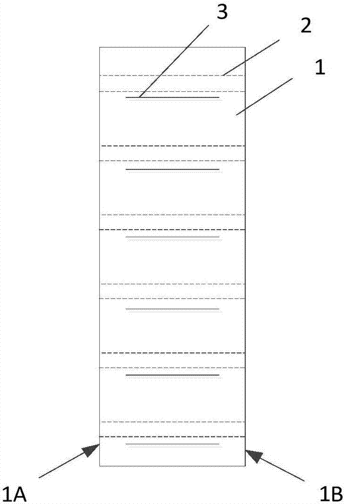
[0026] See figure 1 , is a schematic diagram of a top-view structural principle of a light-transmitting brick in an embodiment of the present invention.

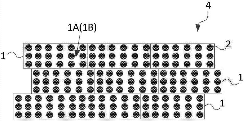
[0027] like figure 1 As shown, the light-transmitting brick includes a brick body 1 and one or more light-transmitting components 2, and the two sides of the brick body 1 that are not adjacent to other brick bodies 1 or walls are respectively defined as the first side 1A and the second side 1B, the light-transmitting components 2 are distributed in the brick body 1, one end of each of the light-transmitting components 2 is located on the first side 1A, and the other end is located on the second side 1B, wherein each light-transmitting component 2 has at least A reinforcing rib 3 is connected / each of the light-transmitting parts is connected with at least one reinforcing rib 3 , and the reinforcing rib is arranged in the brick body 1 .

[0028] By connecting reinforcing ribs on the light-transmitting part, the strength of t...

Embodiment approach 1

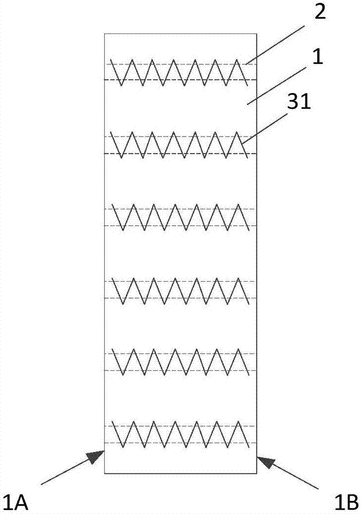
[0032] See image 3 , is a schematic diagram of an implementation principle of the structure of the light-transmitting part and the reinforcing rib in the light-transmitting brick of the present invention. As shown in the figure, the reinforcing rib 3 can be a wire body 31 wound and connected with the light-transmitting part 2 . Wherein, the wire body 31 may be iron wire, copper wire, aluminum wire, cotton wire and the like. In specific implementation, iron wire may be preferred.

Embodiment approach 2

[0034] See Figure 4 , is a schematic diagram of another implementation principle of the structure of the light-transmitting part and the reinforcing rib in the light-transmitting brick of the present invention. As shown in the figure, the reinforcing rib 3 can be a tube body 32 that passes through or covers the light-transmitting part 2 . Wherein, the pipe body 32 may be a steel pipe or a plastic pipe.

[0035] Specifically, see Figure 5 ,for Figure 4 A structural schematic diagram of an implementation of the middle tube body, as shown in the figure, the tube body 32 can be a fastener that can be opened and closed freely. The fastener can have such a structure: one end of the fastener is hinged to realize relative free rotation, and the other end is freely connected to realize free opening and closing connection (that is, it can be freely opened and closed in the K direction or in the opposite direction). When it is on the light-transmitting part, the light-transmitting ...


PUM


Abstract

The invention provides a light transmitting brick and a preparation method thereof. The light transmitting brick includes a brick body and one or more light transmitting components. The light transmitting components are distributed in the brick body, one end of each light transmitting component is located on a first side face, and the other end of each light transmitting component is located on asecond side face; at least one reinforcing rib is connected on each light transmitting component or each light transmitting component is at least connected with one reinforcing rib, and the reinforcing ribs are arranged in the brick body. In addition, according to the preparation method for the light transmitting brick, plastic optical fibers continuously and successively penetrate into a plurality of pairs of through holes, so that the optical fibers between the pairs of through holes are kept a tight state so as to be not easily deformed. The problems that the light transmitting brick is easily extruded to deform in the preparation process and the optical fibers and the brick body are easy to fall off or loose during demolding are well solved.

Description

technical field [0001] The invention relates to the field of optical fiber technology, in particular to a light-transmitting brick and a preparation method thereof. Background technique [0002] Prior art D1 (application number: CN2017201426231) discloses a light-transmitting fiber optic brick. The fiber optic brick is realized by setting a plurality of light-transmitting parts in the brick body. The fiber optic brick can realize the intercommunication of light on both sides of the brick body. Increase the brightness of the darker side, and at the same time, the ends of the light-transmitting parts can be arranged on the surface of the brick body of the fiber optic brick in a certain order to form a pattern and increase the aesthetics of the brick body. [0003] However, if the above-mentioned optical fiber bricks are to be processed during the specific implementation process, the following difficulties are found: first, the light-transmitting parts are regularly arranged in...

Claims


Application Information

Patent Timeline
IPC IPC(8): E04C1/39G02B7/00
CPCG02B7/00E04C1/39
Inventor 庞方亮王亚辉王勇武冉印
Owner CENTURY OPTICOMM CO LTD
Why Eureka
Try Eureka