High-strength self-locking structure

A self-locking structure, high-strength technology, applied in the direction of connecting components, pins, mechanical equipment, etc., can solve the problem that expansion screws cannot achieve high-strength fixation, and achieve the effect of facilitating secondary installation and reversible structure

Inactive Publication Date: 2018-05-08
陈卫
View PDF0 Cites 0 Cited by
  • Summary
  • Abstract
  • Description
  • Claims
  • Application Information

AI Technical Summary

Problems solved by technology

[0005] The purpose of the present invention is to solve the problem that the existing expansion screws cannot achieve high-strength fixation, and provide a high-strength self-locking structure, which can quickly achieve high strength and have stable fixation, and can be applied to other devices , can be used in large industrial

Method used


Image

  • High-strength self-locking structure
  • High-strength self-locking structure
  • High-strength self-locking structure

Examples


Embodiment

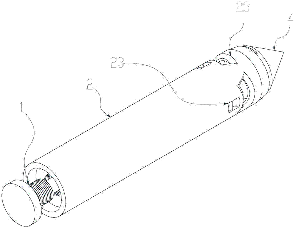
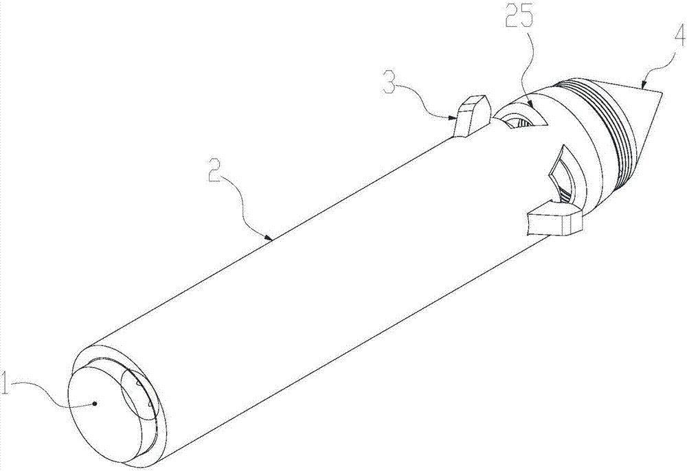
[0028] like Figure 1~4 The shown high-strength self-locking structure includes a fixed push rod 1, a fixed cylinder 2 and a fixed lock 3, and the fixed cylinder 2 is respectively provided with a fixed slideway 21, a lock chamber 22 and a lock through hole 23 . There are one or more fixed latches 3 mentioned above. The number of the lock through holes 23 matches the fixed lock 3, the fixed lock 3 is divided into a self-tapping part 31 and a fixed tail 32, the self-tapping part 31 is placed in the lock through hole 23, and the fixed tail 32 Placed in the locking chamber 22 , the outer diameter of the fixed tail portion 32 is larger than the inner diameter of the locking through hole 23 , and the outer diameter of the self-tapping portion 31 is smaller than the inner diameter of the locking through hole 13 . The above-mentioned fixed propulsion rod 1 is movably socketed in the fixed slideway 11 .

[0029] In order to ensure that the fixed buckle 3 can firmly form a tight fit ...


PUM


Abstract

The invention relates to a fixing device, in particular to a high-strength self-locking structure. The high-strength self-locking structure comprises a fixing push rod, a fixing cylinder and fixing lock catches; a fixing slide way, lock catch chambers and lock catch through holes are separately formed inside the fixing cylinder; one or more fixing lock catches are arranged; the amount of the lockcatch through holes is matched with that of the fixing lock catches; each fixing lock catch is divided into a self tapping part and a fixing tail part; each self tapping part is placed inside the corresponding lock catch through hole; each fixing tail part is placed inside the corresponding lock catch chamber; the outer diameter of each fixing tail part is larger than the inner diameter of the corresponding lock catch through hole; the outer diameter of each self tapping part is smaller than the inner diameter of the corresponding lock catch through hole; and the fixing push rod is movably connected to the interior of the fixing slide way in a muff-coupling manner.

Description

technical field [0001] The invention relates to a fixing device, in particular to a high-strength self-locking structure. Background technique [0002] Most of the expansion screws or similar structures used in the market today are used to fix the structure of the wall. The structure is stable, but the use is cumbersome and requires repeated rotations, and its parts are easy to lose weight. For a structure that requires a large number of expansion screws Often, a lot of time and energy are wasted. [0003] In reality, everything is targeted, and a targeted solution is the best. When applied to different scenarios, for some structures that need to be fixed for a long time and fixed quickly, there is no targeted solution. best solution. [0004] Moreover, its strength is often only suitable for household use, and the fast fixing device for industry has not been provided on the market. Contents of the invention [0005] The purpose of the present invention is to solve the ...

Claims


Application Information

Patent Timeline
Patent Type & Authority Applications(China)
IPC IPC(8): F16B13/06
CPCF16B13/066
Inventor 陈炜
Owner 陈卫
Why Eureka
Try Eureka