Fluid pipeline leakage source positioning system and method

A fluid pipeline and positioning system technology, applied in pipeline systems, gas/liquid distribution and storage, mechanical equipment, etc., can solve problems such as fluid pipeline leakage and inaccurate location of fluid pipeline leakage sources, and achieve strong anti-interference ability and high precision High, wide-ranging effects

Active Publication Date: 2018-05-08
JILIN PROVINCE BAIRUISHENG SCI & TECH DEV
View PDF6 Cites 7 Cited by
  • Summary
  • Abstract
  • Description
  • Claims
  • Application Information

AI Technical Summary

Problems solved by technology

[0004] The purpose of the present invention is to provide a fluid pipeline leakage source location system and method, which solves the problem of inaccurate location of the leakage source in the fluid pipeline calculated by using a fixed sound wave propagation velocity in the prior art

Method used


Image

  • Fluid pipeline leakage source positioning system and method
  • Fluid pipeline leakage source positioning system and method
  • Fluid pipeline leakage source positioning system and method

Examples


Embodiment 1

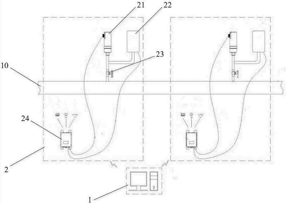
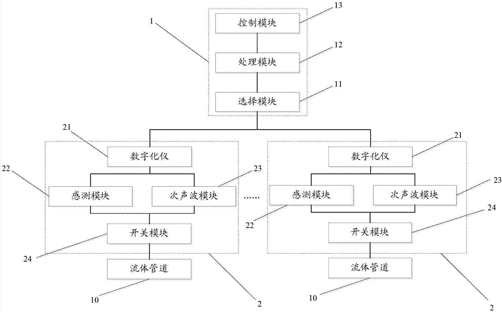
[0050] see figure 1 with figure 2 , a fluid pipeline leakage source locating system provided in this embodiment includes a master station unit 1 and n substation units 2, each substation unit 2 communicates with the fluid pipeline 10, and the n substation units 2 are along the direction of the fluid pipeline 10 Distributed sequentially, wherein the master station unit 1 includes a selection module 11, a processing module 12 and a control module 13 connected in sequence, and the selection module 11 is interactively connected with each substation unit 2 respectively; n≥2,

[0051] The substation unit 2 is used to sense the fluid leakage signal, and release the infrasonic wave according to the release control signal;

[0052] The selection module 11 is used to determine the first n-1 substation unit 2 that receives the fluid leakage signal, and determine the second nth substation unit 2 that receives the fluid leakage signal;

[0053] The control module 13 is configured to sen...

Embodiment 2

[0070] Please refer to 4, an embodiment of the present invention provides a method for locating a leak source of a fluid pipeline, including:

[0071]Sense the fluid leakage signal and release the infrasonic wave according to the release control signal;

[0072] determining the first (n-1)th substation unit 2 that receives the fluid leakage signal, and determining the second nth substation unit 2 that receives the fluid leakage signal;

[0073] When the n-1th substation unit 2 senses the fluid leakage signal, send the release control signal to the n-1th substation unit 2;

[0074] According to the moment t when the n-1th substation unit 2 releases the infrasonic wave 1 , the moment t when the nth substation unit 2 senses the infrasound wave 2 , the time difference t between the nth substation unit 2 and the n-1th substation unit 2 sensing the fluid leakage signal 3 , the distance d between the n-1th sub-station unit 2 and the n-th sub-station unit 2 is calculated to obtain ...


PUM


Abstract

The invention discloses a fluid pipeline leakage source positioning system and method, and relates to the technical field of pipeline detection. According to the fluid pipeline leakage source positioning system and method, the problem that a leakage source position in a fluid pipeline obtained through calculation by a fixed sound wave propagation speed in the prior art is inaccurate is solved. Thefluid pipeline leakage source positioning system comprises a master station unit and n substation units, each sub-station unit communicates with a fluid pipeline, furthermore, the n sub-station unitsare sequentially distributed in the direction of the fluid pipeline, and the main station unit comprises a selection module, a processing module and a control module, wherein the selection module isin interactive connection with each of the sub-station units; and n is larger than or equal to 2. According to the technical scheme, the fluid pipeline leakage source positioning method comprises thefluid pipeline leakage source positioning system, and the fluid pipeline leakage source positioning system is used for detecting a pipeline leakage source.

Description

technical field [0001] The invention relates to the technical field of pipeline detection, in particular to a fluid pipeline leakage source locating system and method. Background technique [0002] In recent years, catastrophic accidents caused by oil and gas pipeline leakage have occurred frequently, and the safe operation and maintenance of pipelines have been threatened and challenged. Therefore, it is necessary to use advanced scientific means to establish a pipeline safety pre-alarm system, monitor fluid leakage accidents in pipelines in real time through effective technical means, accurately issue leakage alarms and quickly locate them, so that production units can start corresponding emergency plans and reduce similar safety hazards. Accidents happen. [0003] At present, the monitoring methods for fluid leakage in pipelines mainly include: pressure point analysis method, negative pressure wave method, flow difference monitoring method, optical cable monitoring metho...

Claims


Application Information

Patent Timeline
Patent Type & Authority Applications(China)
IPC IPC(8): F17D5/06
CPCF17D1/005F17D5/06
Inventor 杨凯
Owner JILIN PROVINCE BAIRUISHENG SCI & TECH DEV
Why Eureka
Try Eureka