
Rotation dynamic sealing device

A rotary sealing and water sealing technology, applied in the components of pumping devices for elastic fluids, machines/engines, liquid fuel engines, etc. Simple and convenient installation effect

Inactive Publication Date: 2016-09-07
XIANGTAN ELECTRIC MFG CORP LTD
View PDF6 Cites 0 Cited by
  • Summary
  • Abstract
  • Description
  • Claims
  • Application Information

AI Technical Summary

Problems solved by technology

[0002] The working medium of the water pump is water, oil, acid-base liquid, emulsion and other liquids. When the working medium enters the bearing side from the water chamber side along the rotating shaft, it will destroy the lubricating oil film of the bearing ball body, reduce the bearing capacity, and even cause bearing corrosion. , seriously reducing the service life of the bearing, so it is necessary to separate the lubricating oil and the working medium in the bearing chamber
[0003] In general, the water pump is installed with two rotating dynamic seals along the shaft to seal the working medium on the side of the water chamber. The first seal is in direct contact with the working medium and is lubricated by the working medium, while the second seal will be in a dry friction state for a long time , seriously reducing its service life
Moreover, the water seal ring and the oil seal on the bearing side are independent parts, which need to be installed separately, and the operation is cumbersome, especially when the shaft diameter is large, the installation difficulty is greatly increased

Method used


Image

  • Rotation dynamic sealing device
  • Rotation dynamic sealing device
  • Rotation dynamic sealing device

Examples


Embodiment Construction

[0016] The present invention will be described in further detail below in conjunction with the accompanying drawings and embodiments.

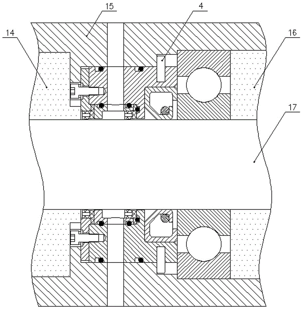
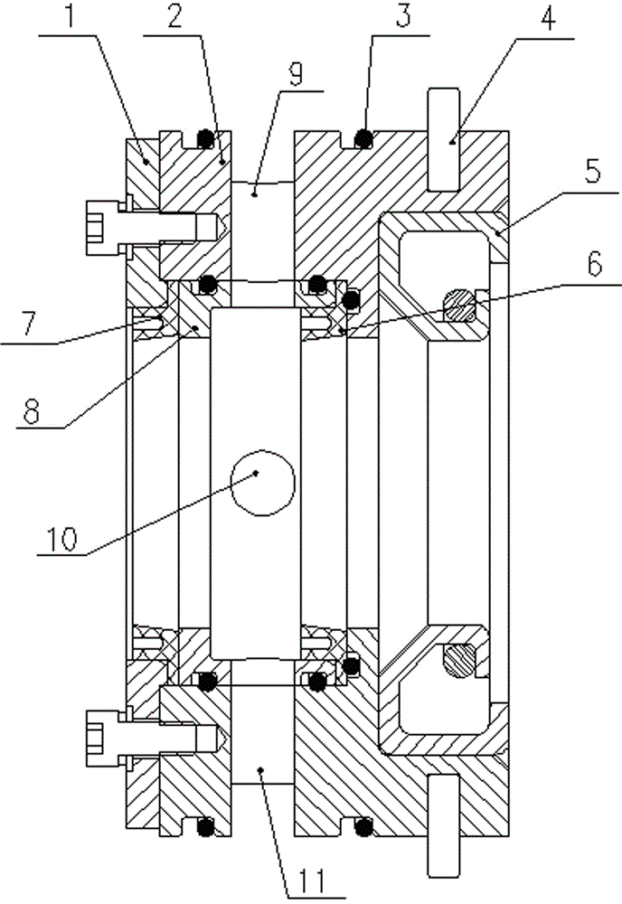
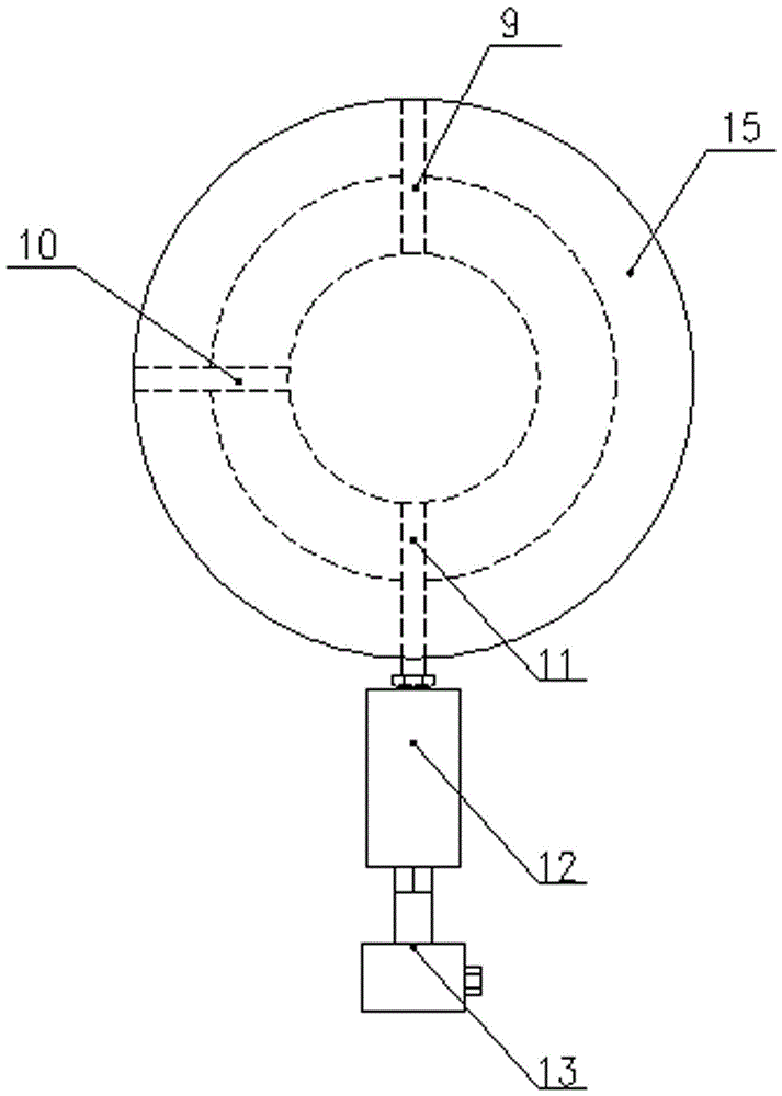
[0017] Referring to the drawings, it includes the first water seal 7, the second water seal 6, the oil seal 5, skeleton I1, skeleton II2, skeleton III8, O-shaped rubber ring 3 and cylindrical pin 4, skeleton I1, skeleton II2 and The assembly surface composed of skeleton III 8 is equipped with O-shaped rubber ring 3 to realize static sealing, and the first water seal 7, the second water seal 6, and the oil seal 5 are arranged in sequence from the water chamber side 14 to the bearing side 16 of the rotating shaft 17, The oil seal 5 is a skeleton oil seal, and the opening of the oil seal 5 faces the bearing side 16. After the skeleton I1, skeleton II2, and skeleton III8 are fixed as a whole, two seals are formed on the inner side which are in contact with the first water seal 7 and the second water seal 6. Matching sealing groove and fixed suppor...


PUM


Abstract

The invention relates to a rotation dynamic sealing device. A first water seal, a second water seal and an oil seal are sequentially arranged from a water cavity side to a bearing side of a rotary shaft and a framework I, a framework II and a framework III define two seal grooves which are matched with the first water seal and the second water seal on the inner side after being integrally fixed and fixedly support the first water seal and the second water seal; an oil lubricating cavity used for lubricating the second water seal is formed between the first water seal and the second water seal; the first water seal, the second water seal and the oil seal are in interference fit with the rotary shaft correspondingly; and the framework I, the framework II and the framework III are in clearance fit with the rotary shaft correspondingly. According to the rotation dynamic sealing device, due to the fact that the oil lubricating cavity is added, the dry friction state of the second seal ring is effectively avoided; and due to the fact that the frameworks are in an integrated structure, installation is easy and convenient, and particularly straight pins can effectively prevent the whole sealing device from rotating along the rotary shaft; and an oil-water alarm device can monitor the leakage situation of the first water seal in real time.

Description

technical field [0001] The invention relates to the field of mechanical seals, in particular to a rotary dynamic seal device. Background technique [0002] The working medium of the water pump is water, oil, acid-base liquid, emulsion and other liquids. When the working medium enters the bearing side from the water chamber side along the rotating shaft, it will destroy the lubricating oil film of the bearing ball body, reduce the bearing capacity, and even cause bearing corrosion. , seriously reducing the service life of the bearing, so it is necessary to separate the lubricating oil and the working medium in the bearing chamber. [0003] In general, the water pump is installed with two rotating dynamic seals along the shaft to seal the working medium on the side of the water chamber. The first seal is in direct contact with the working medium and is lubricated by the working medium, while the second seal will be in a dry friction state for a long time , seriously reducing ...

Claims


Application Information

Patent Timeline
Patent Type & Authority Applications(China)
IPC IPC(8): F04D29/10F04D15/00
CPCF04D29/106F04D15/0077
Inventor 陈纪军张俊何中石程鹏尹曾峰
Owner XIANGTAN ELECTRIC MFG CORP LTD
Learn More