Spiral belt winding guide concentric launching cylinder

A launch tube and screw technology, which is applied in the field of space launch, can solve the problems affecting the safety of missile launch and the temperature rise of the missile wall, and achieve the effects of easy popularization, improvement of pressure and simple principle.

Pending Publication Date: 2018-05-08
ANHUI UNIVERSITY OF TECHNOLOGY
View PDF1 Cites 8 Cited by
  • Summary
  • Abstract
  • Description
  • Claims
  • Application Information

AI Technical Summary

Problems solved by technology

[0005] The above-mentioned patented scheme can be adapted to the launch of winged missiles and can guide the gas, but the main problem is that the gas discharged from the launch tube will sur

Method used


Image

  • Spiral belt winding guide concentric launching cylinder
  • Spiral belt winding guide concentric launching cylinder
  • Spiral belt winding guide concentric launching cylinder

Examples


Embodiment 1

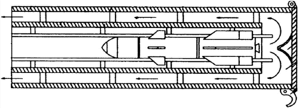
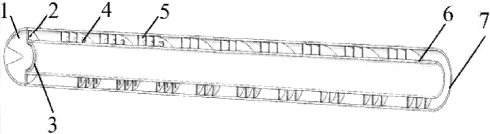
[0035] combine figure 2 , a helically wound tape-guiding concentric launching tube of the present embodiment, comprising an inner tube 6, an outer tube 7 and a diversion cone 1, the inner tube 6 and the outer tube 7 are arranged coaxially, and the diversion cone 1 is fixedly connected to the outer tube 7 ends. The annular cavity between the inner cylinder 6 and the outer cylinder 7 is used for exhausting combustion exhaust gas, and a spiral winding belt 5 surrounds the annular cavity, so that the gas entering the annular cavity after passing through the diversion cone 1 is discharged around the spiral cavity. The spiral winding belt 5 circles along the inner cylinder 6, separates the annular cavity, and forms a spiral cavity. The pitch of the helical winding belt 5 can be adjusted according to the minimum fluid resistance.

[0036] With one end close to the diversion cone 1 as the bottom end and the other end as the outer end, a spiral winding belt 5 wraps around from the b...

Embodiment 2

[0046]The basic structure of the spiral-wound flow-guiding concentric launching tube of this embodiment is the same as that of Embodiment 1, and the improvement is that there are two spiral-wound belts 5, and the pitches of each helically-wound belt 5 are the same, and the spiral-wound belts 5 have the same pitch. The distance between the end of the belt 5 close to the diversion cone 1 and the end of the inner cylinder 6 is 2 times the pitch, so that the gas can quickly enter the annular cavity at the entrance, and the lower end point of the spiral winding belt 5 is flush, and the same vertical On the cross-section of the axis, so that the gas can enter each cavity at the same time.

[0047] As a preferred solution, the two helical belts 5 can be distributed at equal intervals in the circumferential direction to form two helical chambers, and the exhaust gas is discharged around the helical chambers. The distance between the top of the spiral winding belt 5 and the top of the ...

Embodiment 3

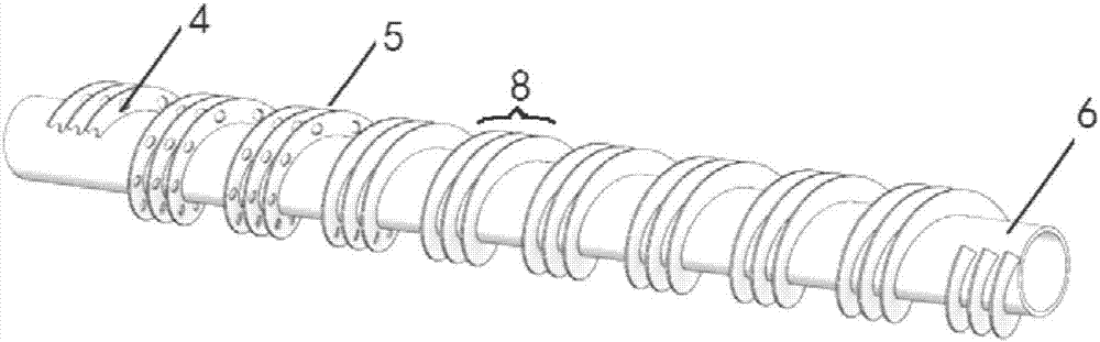
[0050] to combine image 3 , a kind of helical-wound flow-guiding concentric launching tube of this embodiment, its basic structure is the same as that of embodiment 2, the improvement is that: in this embodiment, three helical-wound belts 5 are arranged, and the helically-wound belts 5 are adjacent to Arranged to form a helical winding body 8, the pitch of the helical winding body 8 is the same as that of the helical winding belt 5. But the difference is that a small spiral cavity is formed between the spiral winding strips 5 in the spiral winding body 8 , while the spiral winding body 8 as a whole has a larger spiral cavity.

[0051] In this embodiment, the distance between the helical winding belt 5 and the end of the inner cylinder 6 is a single pitch, and the distance between the top of the helical winding belt 5 and the top of the inner cylinder 6 is 20 mm. In this embodiment, the number of support plates 2 can be set to 3 as a preference, and 3 The support plates 2 are...


PUM


Abstract

The invention discloses a spiral belt winding guide concentric launching cylinder, and belongs to the field of space launching. The spiral belt winding guide concentric launching cylinder comprises aninner cylinder, an outer cylinder and a guide cone; and spiral winding belts are encircled in an annular cavity between the inner cylinder and the outer cylinder, so that guided missile gas enteringthe annular cavity after passing through the guide cone is exhausted around a spiral cavity. Axial guide holes are formed in the ends, near the guide cone, of the spiral winding belts; and the guide holes in the same spiral winding belt are peripherally arranged at equal intervals. Through arrangement of the spiral winding belts, the time of thoroughly discharging gunpowder gas from the annular cavity is delayed; and the tail gas is exhausted in a direction deviated from the axis, so that the ablation influence on the guided missile wall surface during launching is prevented, and improvement of the guided missile launching safety is facilitated.

Description

technical field [0001] The invention relates to the field of space launch technology, in particular to a spiral-wound tape-guided concentric launch tube. Background technique [0002] Because the concentric cylinder launching structure has the functions of simple structure, convenient operation and self-guiding, it is widely used in vehicle-mounted and ship-borne weapons. For missiles launched from concentric cylinders, the high-temperature, high-velocity gas generated during launch is discharged upwards through the annular space between the two cylinders after being deflected by the bottom deflector. [0003] At present, during the launching process of the concentric cylinder, after the missile gas flow is ejected, it will undergo secondary combustion with the oxygen in the launching cylinder. After the oxygen in the launching cylinder is consumed, the gas that has not undergone secondary combustion will pass through the diversion of the diversion cone. The gas enters betw...

Claims


Application Information

Patent Timeline
IPC IPC(8): F41F1/00
CPCF41F1/00
Inventor 胡晓磊郭佳肄刘涛孙船斌徐张宝刘庆运谢能刚
Owner ANHUI UNIVERSITY OF TECHNOLOGY
Why Eureka
Try Eureka