A device and method for detecting symmetry of rudder shaft grooves of rudder shaft parts

A detection method and technology of symmetry, applied in the direction of measuring device, mechanical measuring device, using mechanical device, etc., can solve problems such as high cost, affecting production progress, occupying measuring equipment, etc., achieving low cost, improving processing efficiency, and easy operation. Effect

Active Publication Date: 2020-06-19
CAPITAL AEROSPACE MACHINERY +1
View PDF5 Cites 0 Cited by
  • Summary
  • Abstract
  • Description
  • Claims
  • Application Information

AI Technical Summary

Problems solved by technology

The traditional method needs to use a three-coordinate measuring machine for measurement, which is costly, occupies measuring equipment, and seriously affects the production schedule

Method used


Image

  • A device and method for detecting symmetry of rudder shaft grooves of rudder shaft parts
  • A device and method for detecting symmetry of rudder shaft grooves of rudder shaft parts
  • A device and method for detecting symmetry of rudder shaft grooves of rudder shaft parts

Examples


Embodiment 1

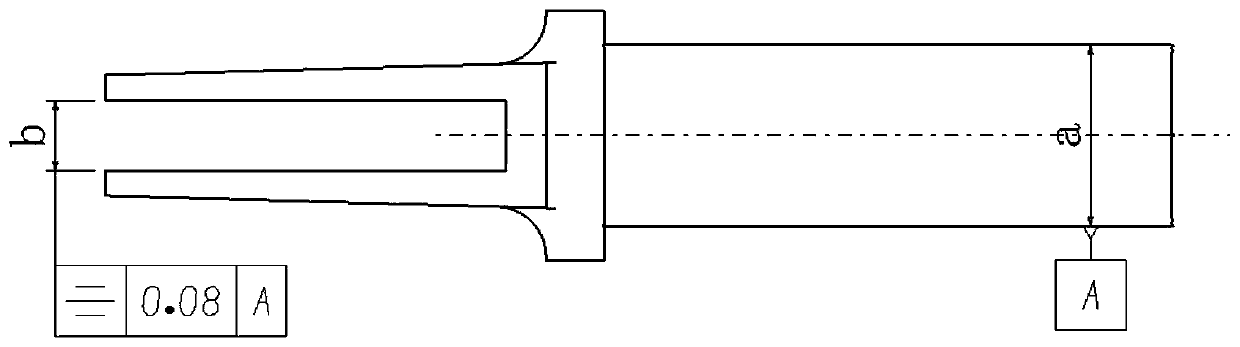
[0027] The rudder shaft groove structure of rudder shaft parts is as follows: figure 1 shown.

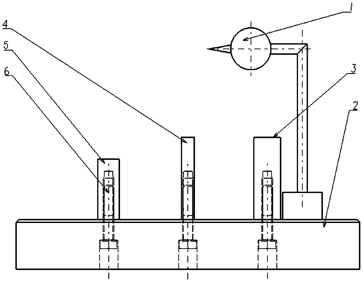
[0028] Such as figure 2 As shown, a device for detecting the symmetry of the rudder shaft groove of the rudder shaft parts according to the present invention includes a base 2, and the gauge block 1 3 and the gauge block 2 4 are connected side by side by connecting screws 6 above the base 2 , gauge block three 5; dial gauge 1 is magnetically adsorbed on the base 2, and is set near gauge block one 3, gauge block two 4, or gauge block three 5 as required during measurement; said gauge one 3, gauge Block two 4, measuring block three 5 are set for the rudder shaft 8 adapting to different groove widths, can dismantle.

[0029] The height of the contacts of the dial indicator 1 can be adjusted so that the contacts contact the tapered surfaces of the rudder shaft 8 at different heights.

[0030] The dimensions of the gauge block one 3, gauge block two 4, and gauge block three 5 can be ...

Embodiment 2

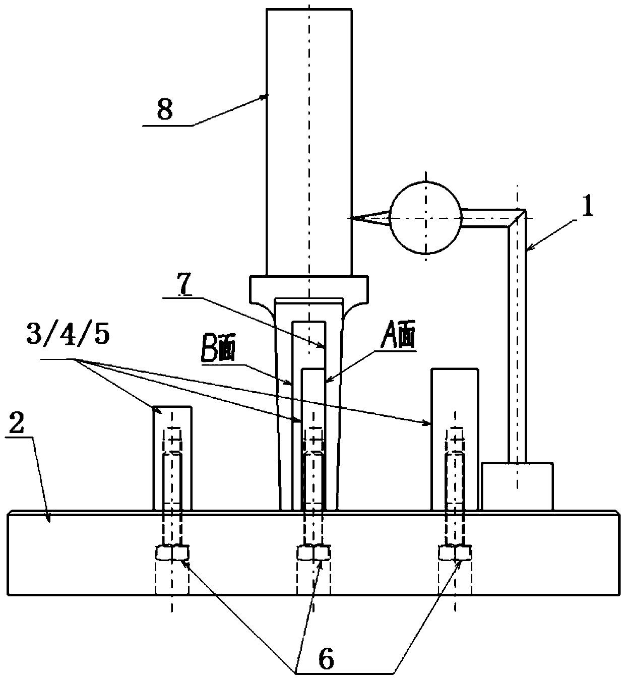
[0034] Such as figure 2 As shown, the method for detecting the symmetry of the rudder shaft groove of the rudder shaft part using the rudder shaft part rudder shaft groove symmetry detection device described in Embodiment 1 comprises the following steps:

[0035] Step (a), when measuring, make a side A in the rudder shaft groove 7 of the rudder shaft parts close to one of the gauge block 1 3, the gauge block 2 4 or the gauge block 3 5;

[0036] Step (b), adjust the position of the contact of dial indicator 1 on the base 2, make the contact of dial indicator 1 touch the cone surface of rudder shaft 8, move the rudder shaft 8 along the surface of the gauge block, and record the maximum reading of dial indicator 1;

[0037] Step (c), turning the rudder shaft 8 so that the other side B in the rudder shaft groove 7 is close to one of gauge block 1 3, gauge block 2 4 or gauge block 3 5;

[0038] Step (d), adjust the position of the contact of dial indicator 1 on the base 2 so that...

Embodiment 3

[0041] Such as figure 2 As shown, the method for detecting the symmetry of the rudder shaft groove of the rudder shaft part using the rudder shaft part rudder shaft groove symmetry detection device described in Embodiment 1 comprises the following steps:

[0042] Step (a), when measuring, make a side A in the rudder shaft groove 7 of the rudder shaft parts close to one of the gauge block 1 3, the gauge block 2 4 or the gauge block 3 5;

[0043] Step (b), adjust the position of the contact of dial indicator 1 on the base 2, make the contact of dial indicator 1 touch the cone surface of rudder shaft 8, move the rudder shaft 8 along the surface of the gauge block, and record the maximum reading of dial indicator 1;

[0044] Step (c), turning the rudder shaft 8 so that the other side B in the rudder shaft groove 7 is close to one of gauge block 1 3, gauge block 2 4 or gauge block 3 5;

[0045] Step (d), adjust the position of the contact of dial indicator 1 on the base 2 so that...


PUM


Abstract

The invention provides a device and a method for measuring the symmetry of a rudder shaft slot of a rudder shaft part. A gauge block I, a gauge block II and a gauge block III are connected side by side above a base through connecting screws. A dial gauge is adsorbed to the base by magnetic force, and is arranged near the gauge block I, the gauge block II or the gauge block III as needed during measurement. The gauge block I, the gauge block II and the gauge block III are set to adapt to rubber shafts with different slot width, and can be disassembled. During measurement, one side in a rudder shaft slot of a rudder shaft part is put close to one gauge block; the contact of the dial gauge contacts the conical surface of the rubber shaft, the rubber shaft is moved along the surface of the gauge block, and the maximum reading of the dial gauge is recorded; the rubber shaft is turned so the other side in the rubber shaft slot is put close to the gauge block; the contact of the dial gauge contacts the conical surface of the rubber shaft, the rubber shaft is moved along the surface of the gauge block, and the maximum reading of the dial gauge is recorded again; and the absolute value of the difference between the two readings of the dial gauge is the symmetry. The device of the invention has a simple structure and a good application effect. The method of the invention is easy to operate, and costs low.

Description

technical field [0001] The invention belongs to a device for detecting symmetry of groove parts, in particular to a device and method for detecting symmetry of rudder shaft grooves of rudder shaft parts. Background technique [0002] The rudder shaft part is a key part in the transmission assembly of the missile weapon, and its machining accuracy is directly related to the flight control accuracy of the missile weapon. Therefore, there are very strict requirements on the accuracy of shape, position and size, which is mainly reflected in the requirements on the symmetry of the rudder shaft groove. Such as figure 1 shown. [0003] The machining process of the rudder shaft groove needs to go through multiple processes such as wire-cut roughing, wire-cut finishing, rough milling, and fine milling. In order to control the machining accuracy and calculate the machining allowance accurately, it is necessary to measure the symmetry of the rudder shaft groove after each process is...

Claims


Application Information

Patent Timeline
Patent Type & Authority Patents(China)
IPC IPC(8): G01B5/252G01B5/00
CPCG01B5/0018G01B5/252
Inventor 王建舒荣辉杜红娥王金龙
Owner CAPITAL AEROSPACE MACHINERY
Why Eureka
Try Eureka