Cable measurement device

A measuring device and cable technology, applied in measuring devices, instruments, etc., can solve problems such as inflexible operation, inaccurate measurement, and difficulty in finding cable problems, so as to prevent inaccurate measurement, stable and accurate measurement, and small size Effect

Active Publication Date: 2018-05-08
中铁建电气化局集团南方工程有限公司
View PDF6 Cites 5 Cited by
  • Summary
  • Abstract
  • Description
  • Claims
  • Application Information

AI Technical Summary

Problems solved by technology

[0002] The meter measurement of the cable passes through the metering device. In order to prevent the vibration of the cable during the measurement process, resulting in inaccurate metering, the invention patent application No. 2007201297345 "Precise meter meter device" uses a conveyor belt to increase the contact between the metering device and the cable area method, but this method is large in size in practical applications, and its operation is not flexible, so it is difficult to promote
During the continuous movement of the cable, it may come out from the side of the conveyor belt, resulting in the loss of previous efforts in cumulative measurement, and all measurement data needs to be measured from the beginning, further reducing work efficiency
[0003] The currently disclosed cable meter measuring device can only measure the length of the cable, and the diameter of the cable directly affects the quality and engineering planning of the cable, and any local problem in the entire cable will directly affect the entire cable. The quality of the cable
The detection of the continuous change of the cable diameter is of special significance for the quality inspection of the cable and the discovery of the sudden change of the local wire diameter of the cable. Identify possible problems in cables

Method used


Image

  • Cable measurement device
  • Cable measurement device
  • Cable measurement device

Examples


Embodiment Construction

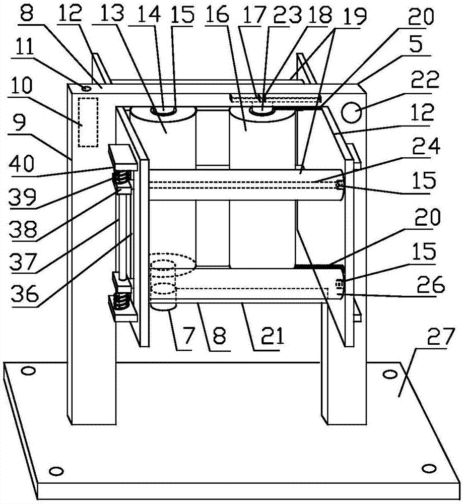
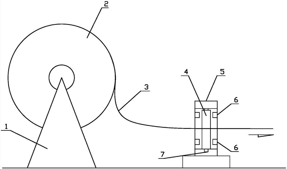
[0023] Below in conjunction with accompanying drawing and embodiment the present invention is further described: as figure 1 The cable measuring device shown in is used for real-time length and wire diameter measurement of the cable when it is released from the cable drum at the construction site.

[0024] Such as figure 1 The cable measuring device is provided with a horizontal base, and an outer frame 9 fixed to the base 27, and the outer frame 9 is provided with a fixed rod 8 for connecting a pair of rollers. The outer frame is provided with a fixed roller 13 and a measuring roller 16 vertically arranged with the fixed rod. The direction setting of fixed bar 13 and measuring roller 16 is not limited, only need to be stably fixed with outer frame, or become a part of outer frame 9, as an embodiment in figure 1 , 2 Adopt the fixed rod that horizontally arranges in the middle, and fixed rod 8 is set to a pair of high and low positions, is respectively referred to as top rod...


PUM


Abstract

The invention provides a cable measurement device. A fixed roll and a measurement roll parallel to each other are arranged in an outer frame. A movable shaft can slide along a fixed rod. A clamping spring is connected between one end part of the movable shaft and the outer frame on the outer side of the movable shaft. Clamping rollers arranged in parallel and in pairs is arranged on a plane defined by the fixed shaft and the movable shaft. Two ends of the clamping rollers in pairs both penetrate through a support frame and can slide towards each other. One movable roller is provided with a displacement sensor and is also provided with a length sensor and a measurement circuit. According to the invention, stable and accurate measurement of a cable metering device can be realized; cable release from the metering device when penetrating through the metering device quickly can be prevented during real time measurement of cable length and wire diameter of the cable penetrating through. Besides, the device is small in size and low in weight. The cable can penetrate through the device flexibly without obvious resistance. Offset is not caused in long term large scale measurement and measurement inaccuracy caused to cable jitter can be prevented. Measurement data can be uploaded for centralized analysis and management.

Description

technical field [0001] The invention relates to engineering measurement technology, in particular to a cable measurement device. Background technique [0002] The meter measurement of the cable passes through the metering device. In order to prevent the vibration of the cable during the measurement process, resulting in inaccurate metering, the invention patent application No. 2007201297345 "Precise meter meter device" uses a conveyor belt to increase the contact between the metering device and the cable Area method, but this method has a large volume in practical application, and its operation is not flexible, so it is difficult to promote. During the continuous movement of the cable, it may come out from the side of the conveyor belt, resulting in the loss of previous efforts in cumulative measurement, and all measurement data needs to be measured from the beginning, further reducing work efficiency. [0003] The currently disclosed cable meter measuring device can only m...

Claims


Application Information

Patent Timeline
Patent Type & Authority Applications(China)
IPC IPC(8): G01B21/00
CPCG01B21/00
Inventor 徐键徐斌董科可
Owner 中铁建电气化局集团南方工程有限公司
Why Eureka
Try Eureka