Liquid display device

A technology of liquid crystal display device and liquid crystal panel, applied in the direction of nonlinear optics, instruments, optics, etc., can solve the problems affecting the stability of work performance, the reliability reduction of drive chips, and the high temperature of drive chips, so as to avoid the deterioration of work performance and reduce Influence, the effect of improving reliability

Active Publication Date: 2018-05-08
WUHAN CHINA STAR OPTOELECTRONICS TECH CO LTD
View PDF5 Cites 24 Cited by
  • Summary
  • Abstract
  • Description
  • Claims
  • Application Information

AI Technical Summary

Problems solved by technology

During the operation of the liquid crystal display device, the driver chip itself will generate a large amount of heat radiation, and the backlight module will also generate a large amount of heat radiation. If the distance is very small, the heat radiation generated by the backlight module and the heat radiation generated by the driver chip will superimpose, which will make the temperature of the driver chip too high
The driver chip is an important part for transmitting and processing signals. If its temperature is too high, it will affect the stability of the working performance, which will reduce the reliability of the driver chip and even cause the driver chip to be damaged due to overheating.

Method used


Image

  • Liquid display device
  • Liquid display device
  • Liquid display device

Examples


Embodiment 1

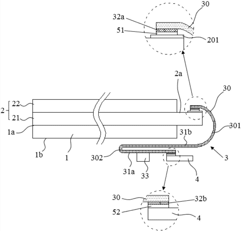
[0029] This embodiment provides a liquid crystal display device, such as figure 1 As shown, the liquid crystal display device includes a backlight module 1 , a liquid crystal panel 2 , a chip on film 3 and a printed circuit board 4 . Wherein, the backlight module 1 and the liquid crystal panel 2 are arranged oppositely, the backlight module 1 includes a light-emitting surface 1a and a back surface 1b opposite to the light-emitting surface 1a, and the liquid crystal panel 2 is arranged on the backlight module. On the light emitting surface 1 a of the group 1 , a signal binding terminal 201 is provided on the front surface 2 a of the liquid crystal panel 2 facing away from the backlight module 1 . Specifically, the liquid crystal panel 2 includes a thin film transistor array substrate 21 and a color filter substrate 22 oppositely arranged, and the signal binding terminal 201 is arranged on an edge of the thin film transistor array substrate 21 .

[0030] Among them, see figure...

Embodiment 2

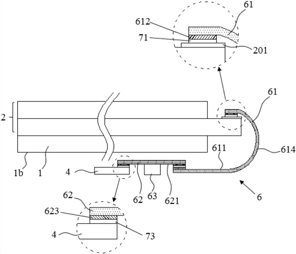
[0037] This embodiment provides a liquid crystal display device. The difference from Embodiment 1 is that the structure of the COF in this embodiment is different from that in Embodiment 1.

[0038] Specifically, see image 3 with Figure 4 , in this embodiment, the COF 6 includes a first flexible circuit board 61 and a second flexible circuit board 62 connected to each other, the first surface 611 of the first flexible circuit board 61 is provided with a first bonding The first binding part 622 , the second binding part 623 and the driver chip 63 are arranged on the first surface 621 of the second flexible circuit board 62 .

[0039] Wherein, the first binding part 612 is located at the first end of the first flexible circuit board 61, and is used to electrically connect the first flexible circuit board 61 to the signal binding end 201 of the liquid crystal panel 2; The second binding part 613 is located at the second end of the first flexible circuit board 61, and is used ...


PUM


Abstract

The invention discloses a liquid display device. The liquid display device comprises a back light module, a liquid crystal panel and a chip on film, wherein the backlight module is composed of a lightemitting surface and a back surface opposite to the light emitting surface; the liquid crystal panel is arranged on the light emitting surface of the backlight module, and the front surface of the liquid crystal panel, which backs to the backlight module, is provided with a signal binding end; the chip on film is composed of a flexible circuit board, a binding unit and a driving chip, the bindingunit and the driving chip are arranged on the first surface of the flexible circuit board, the flexible circuit board is electrically connected to the signal binding end through the binding unit andis bent to extend towards the back surface of the backlight module; in the part of the flexible circuit board which is bent to extend towards the back surface of the backlight module, the first surface of the flexible circuit board comprises a first area back to the backlight module, and the driving chip is connected inside the first area. The liquid display device can reduce influence of heat generated by the backlight module on the driving chip, thereby improving the reliability of the driving chip.

Description

technical field [0001] The invention relates to the field of display technology, in particular to a liquid crystal display device. Background technique [0002] Among flat panel display devices, Liquid Crystal Display (LCD) has the characteristics of small size, low power consumption, relatively low manufacturing cost and no radiation, and occupies a dominant position in the current flat panel display market. [0003] A chip on film (COF) is a driving unit used in a liquid crystal display device, and is usually attached and bonded to the edge of the liquid crystal panel by means of heat and pressure. With the continuous advancement of display technology, display products with narrow bezels (Narrow Bezel) have attracted a large number of consumers because they can enable users to obtain a better viewing experience. In order to obtain a liquid crystal display device with a narrow frame, it is usually necessary to bend the COF from the side of the liquid crystal panel to the b...

Claims


Application Information

Patent Timeline
Patent Type & Authority Applications(China)
IPC IPC(8): G02F1/1345
CPCG02F1/13452G02F1/13454G02F1/13456
Inventor 白宇杰黄俊宏
Owner WUHAN CHINA STAR OPTOELECTRONICS TECH CO LTD
Why Eureka
Try Eureka