Eureka AIR delivers breakthrough ideas for toughest innovation challenges, trusted by R&D personnel around the world.

Sound control module for earphone

A technology for earphones and users, which is applied in the direction of earpiece/earphone accessories, earphone mechanical/electronic switches, microphones, etc., and can solve the problems of large volume, production, and inability to meet thin and miniaturization

Inactive Publication Date: 2018-05-08
MAO BANG ELECTRONICS
View PDF7 Cites 1 Cited by
  • Summary
  • Abstract
  • Description
  • Claims
  • Application Information

AI Technical Summary

Problems solved by technology

However, as far as the existing microphone or button switch is concerned, the volume occupied by itself is relatively large, so that when the existing microphone or button switch is arranged on a printed circuit board, it is not conducive to the thinning of the voice control module. or miniaturization; in addition, the existing push button switch is not only costly, but also limited by the structure of the push button switch, it cannot be produced by surface mount technology (SMT, Surface Mount Technology), that is, the widely used surface mount technology cannot be used (SMT) or related machines to weld and fix the existing button switch on the printed circuit board, so the manufacturing process is relatively complicated, and the manufacturing cost is increased, which is not conducive to the mass production of the voice control module.
[0003] Therefore, the existing voice control module used for earphones has the following disadvantages in component structure, manufacturing process or practical application: First, because the existing microphone assembled will increase the total thickness of the voice control module, causing the voice control module The thickness of the switch is relatively large, which cannot meet the needs of thinning and miniaturization, and is not conducive to the cooperative application between the voice control module and the earphone; secondly, the existing button switch has a high cost and cannot use surface mount technology (SMT) production, which is not conducive to the mass production and application of the voice control module

Method used


Image

  • Sound control module for earphone
  • Sound control module for earphone
  • Sound control module for earphone

Examples


Embodiment Construction

[0021] In order to make the present invention more definite and detailed, the preferred embodiments are listed hereby in conjunction with the following diagrams, and the structure and technical characteristics of the present invention are described in detail as follows:

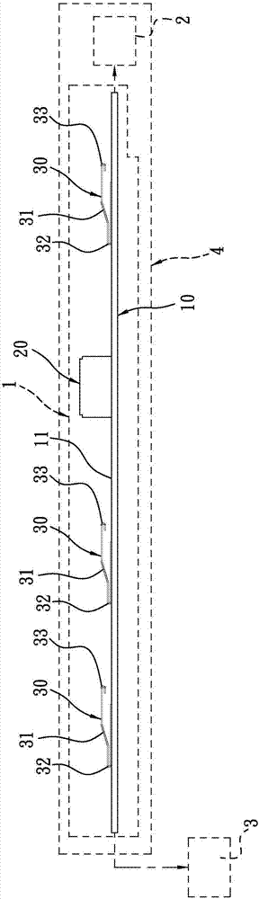
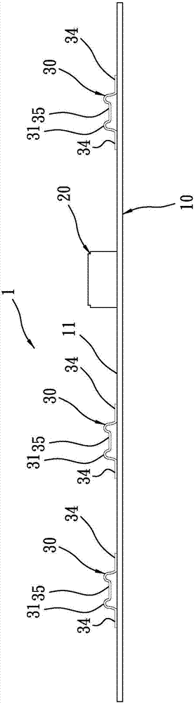
[0022] Such as figure 1 , figure 2 As shown, they are schematic side views of the first embodiment (the micro-ellipse is welded on one side) and the second embodiment (the micro-ellipse is welded on both sides) of the voice control module 10 provided by the present invention. The voice control module 1 for earphones provided by the present invention is electrically connected between an earphone 2 and an electronic device 3, such as figure 1 As shown, one end of the voice control module 10 is electrically connected to an earphone 2, and the other end is electrically connected to an electronic device 3, but this is not intended to limit the present invention, for the user to control the earphone 2 by operatin...


PUM


Abstract

The invention discloses a sound control module for an earphone, and the sound control module is electrically connected between the earphone and an electronic device so as to control the use function of the earphone. The sound control module comprises a long piece-shaped printed circuit board with an electronic circuit for control; an MEMS (micro electro mechanical system) microphone which is welded to the printed circuit board; and at least one miniature elastic-piece switch which employs a miniature elastic piece made of an alloy material as a key, and enables at least one side edge of the miniature elastic piece to be welded to the printed circuit board through the surface adhesion technology. The miniature elastic piece generates elastic displacement when being pressed, so as to touch acorresponding contact on the printed circuit board to achieve the switching effect. Therefore, the sound control module can be enabled to be thin and miniature, and the manufacturing process is simplified, the manufacturing cost is reduced and the utilization efficiency of the sound control module is improved.

Description

technical field [0001] The invention relates to a sound control module for earphones, especially a micro-electromechanical (MEMS) microphone and at least one miniature shrapnel switch on a long sheet-shaped printed circuit board, and the miniature shrapnel switch utilizes surface adhesion technology (SMT) soldered on this printed circuit board. Background technique [0002] The sound control module for earphones referred to in the present invention is electrically connected between an earphone (forming a cube) and an electronic device (such as a mobile phone but not limited) to control the function of the earphone. The structure of the sound control module A microphone and at least one button switch are combined on a printed circuit board. However, as far as the existing microphone or button switch is concerned, the volume occupied by itself is relatively large, so that when the existing microphone or button switch is arranged on a printed circuit board, it is not conducive...

Claims


Application Information

Patent Timeline
Patent Type & Authority Applications(China)
IPC IPC(8): H04R1/10
CPCH04R1/1041H04R2201/10
Inventor 徐振岷吴振嘉
Owner MAO BANG ELECTRONICS
Why Eureka
Eureka Blog
Learn More