

Paging method, communication timing method and apparatuses
A technology of paging timing and paging message, which is applied in the field of communication, can solve the problem of high paging message overhead and achieve the effect of reducing overhead
- Summary
- Abstract
- Description
- Claims
- Application Information
AI Technical Summary
Problems solved by technology
Method used
Image

Examples
Embodiment A1
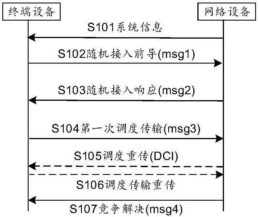
[0538]Embodiment A1: The time unit of message 1 (denoted as S1) and the specific time are specified by random access resource configuration. The time unit of message 2 (marked as S2) is determined according to the subcarrier spacing of message 2; the time unit of message 3 (marked as S3) is determined according to the subcarrier spacing of message 3; the time unit of message 4 (marked as S4) is determined according to the message The subcarrier spacing of 4 is determined. However, since the subcarrier intervals of message 1, message 2, message 3, and message 4 may be different, and there is a sequence relationship in time, it is necessary to consider aligning them in time. Specifically, the sending time of message 2 is determined according to the time when message 1 is sent, and the time of message 2 is determined by the random access response window, including the start time and window length of the random access response window; the sending time of message 3 Determined acco...
Embodiment A2
[0539] Embodiment A2: In an implementation manner, the time unit S2 of the message 2 is determined according to the subcarrier spacing of the message 2 and / or the base station indication information. The start time of the random access response window and the window length can be based on the time unit S2 of message 2, the time unit S1 of message 1, the start time length of the random access response window is k0, and the random access response window length L At least one OK. For example, the time when message 1 is sent is T (based on the time unit S1 of message 1), if the start time of the random access response window is based on time unit S1 and the length of the start time is k0, then the start time of the random access response window The time unit of the start time in message 2 is ceil((T+k0)*S1 / S2); if the start time of the response window is based on the time unit S1 and the length of the start time is k0, then the start time of the random access response window The ...
Embodiment A3
[0540] Embodiment A3: In an implementation manner, the time unit S3 of the message 3 is determined according to the subcarrier spacing of the message 3 and / or the base station indication information. The sending time of message 3 is based on the receiving time n of message 2, the processing delay of message 2 and the uplink and downlink switching delay k1 (predefined or pre-stored in the protocol, or indicated by the base station through signaling configuration), and the offset specified in message 2 At least one of the time k2, the time unit S2 of the message 2, and the time unit S3 of the message 3 is determined. For example, the reception time n of message 2 (based on time unit S2 of message 2), if time k1 is based on time unit S2, and time k2 is based on time unit S2, the sending time of message 3 (in time unit S3 of message 3) is ceil( (n+k1+k2)*S2 / S3); if time k1 is based on time unit S2, and time k2 is based on time unit S3, the sending time of message 3 (in time unit S...
PUM
 Abstract
Description
Claims
Application Information