Precision forging die structure facilitating forging

A technology for precision forgings and molds, which is applied in the direction of manufacturing tools, forging/pressing/hammer devices, forging/pressing/hammering machinery, etc. It can solve the problems of inability to realize forging demoulding, limited mold closing height, and inability to carry out precision forgings, etc. , to achieve the effect of convenient and quick separation, improved quality and simple structure

Inactive Publication Date: 2018-05-11
江苏大洋精锻有限公司
View PDF0 Cites 2 Cited by
  • Summary
  • Abstract
  • Description
  • Claims
  • Application Information

AI Technical Summary

Problems solved by technology

[0002] Most precision forgings are poured by upper and lower dies. Precision forgings may be dislocated during the forging process of upper and lower dies and affect product quality. It is necessary to reduce the error caused by the dislocation of upper and lower dies of precision forgings in order to control product quality in time, and most of the existing precision forgings Forgings will be limited by the closed height of the mold during forging, so it is impossible to achieve smooth demolding of forgings, and it is impossible to forge precision forgings, such as journals, hubs, etc. Production

Method used


Image

  • Precision forging die structure facilitating forging
  • Precision forging die structure facilitating forging
  • Precision forging die structure facilitating forging

Examples


Embodiment 1

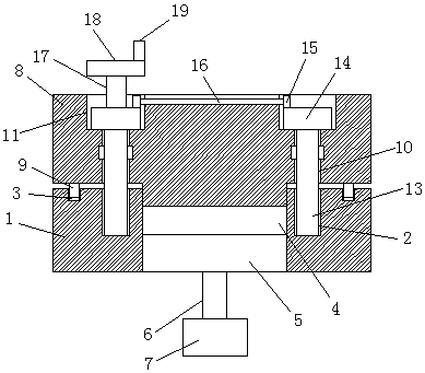
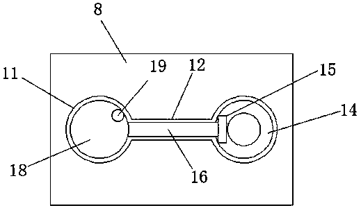
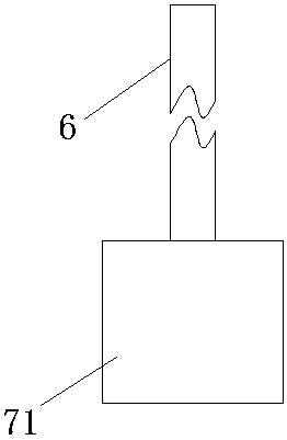
[0020] A die structure for precision forgings that is convenient for forging, including a lower die 1, threaded blind holes 2 are provided on the center of both ends of the lower die 1, guide holes 3 are provided on the outside of the threaded blind holes 2, and the center of the lower die 1 A mold cavity 4 is provided, and a lower mold core plate 5 used in conjunction with the mold cavity 4 is provided. The bottom surface of the lower mold core plate 5 is provided with a lifting rod 6, and the other end of the lifting rod 6 is connected to a power device 7. The power unit 7 includes a cylinder 71 controlled by a manual switch. The output end of the cylinder 71 is connected with a lifting rod 6, which is convenient for the lower mold core plate 5 to be ejected upwards or pulled downwards. The top surface of the lower mold 1 is provided with a The upper mold 8, the bottom surface of the upper mold 8 is respectively provided with a guide post 9 and a threaded through hole 10, the...

Embodiment 2

[0022] A die structure for precision forgings that is convenient for forging, including a lower die 1, threaded blind holes 2 are provided on the center of both ends of the lower die 1, guide holes 3 are provided on the outside of the threaded blind holes 2, and the center of the lower die 1 A mold cavity 4 is provided, and a lower mold core plate 5 used in conjunction with the mold cavity 4 is provided. The bottom surface of the lower mold core plate 5 is provided with a lifting rod 6, and the other end of the lifting rod 6 is connected to a power device 7. The power unit 7 comprises a stepping motor 72 controlled by a manual switch, the output end of the stepping motor 72 is provided with a screw mandrel 73, the screw mandrel 73 is provided with a sliding block 74, and the other end of the sliding block 74 is provided with a lifting rod 6, It is convenient to push out or pull down the core plate 5 of the lower mold. The top surface of the lower mold 1 is provided with an uppe...


PUM


Abstract

The invention discloses a precision forging die structure facilitating forging. The precision forging die structure comprises a lower die, a die cavity is formed in the center of the lower die, a lower die core plate used in cooperation with the die cavity is arranged in the die cavity, a lifting rod is arranged on the bottom face of the lower die core plate, the other end of the lifting rod is connected with a power device, two round grooves are connected through a linear groove, threaded rods are inserted into two threaded through holes, and driven gears used in cooperation are arranged on two driving gears. The precision forging die structure is simple, linkage of the lower die core plate, the lifting rod and the power device is achieved, and use is flexible and convenient; and by meansof the arrangement of the above structure, assembly is facilitated, the assembly time is shortened, the product quality is better improved, the production efficiency is greatly improved, meanwhile, the production cost is reduced, and the die capacity is effectively enlarged.

Description

technical field [0001] The invention relates to the technical field of die structures for precision forgings, in particular to a die structure for precision forgings that is convenient for forging. Background technique [0002] Most precision forgings are poured by upper and lower dies. Precision forgings may be dislocated during the forging process of upper and lower dies and affect product quality. It is necessary to reduce the error caused by the dislocation of upper and lower dies of precision forgings in order to control product quality in time, and most of the existing precision forgings Forgings will be limited by the closed height of the mold during forging, so it is impossible to achieve smooth demolding of forgings, and it is impossible to forge precision forgings, such as journals, hubs, etc. Production. For this reason, need a kind of convenient forging precision forging die structure. Contents of the invention [0003] The object of the present invention is ...

Claims


Application Information

Patent Timeline
Patent Type & Authority Applications(China)
IPC IPC(8): B21J13/02
CPCB21J13/02
Inventor 汤晓东张俊孙建东季斌
Owner 江苏大洋精锻有限公司
Why Eureka
Try Eureka