Double-face chamfering mechanism of gear

A gear, double-sided technology, used in gear cutting machines, components with teeth, gear teeth manufacturing devices, etc., can solve problems such as slow processing speed, gear noise, and scrapped gears

Inactive Publication Date: 2018-05-11
金方明
View PDF0 Cites 2 Cited by
  • Summary
  • Abstract
  • Description
  • Claims
  • Application Information

AI Technical Summary

Problems solved by technology

[0002] Gear is a kind of precision workpiece. With the development of technology, the requirements for gear are getting higher and higher, and gears often produce burrs in the process of machining and forming. These burrs are a major factor affecting the accuracy of gears. The burrs cause the gear to be scrapped, and the burr also makes the gear produce noise during use. Therefore, the edge of the gear needs to be chamfered during the processing of the gear, which can reduce the generation of burrs in the subsequent processing. However, the current general gear chamfering machine, Most of them require workers to cooperate with feeding, and the gears need to be fixed on the station by manual practical bolts. The operation is complicated and affects the processing speed. The gear chamfering work on some production lines usually chamfers the edges and corners of both sides of the gear in sequence. Processing speed is relatively slow

Method used


Image

  • Double-face chamfering mechanism of gear
  • Double-face chamfering mechanism of gear
  • Double-face chamfering mechanism of gear

Examples


Embodiment Construction

[0027] Below in conjunction with accompanying drawing and embodiment of description, specific embodiment of the present invention is described in further detail:

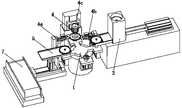
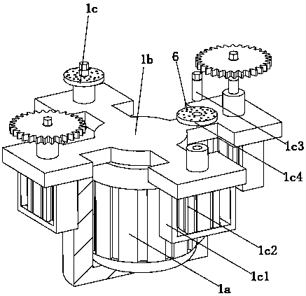
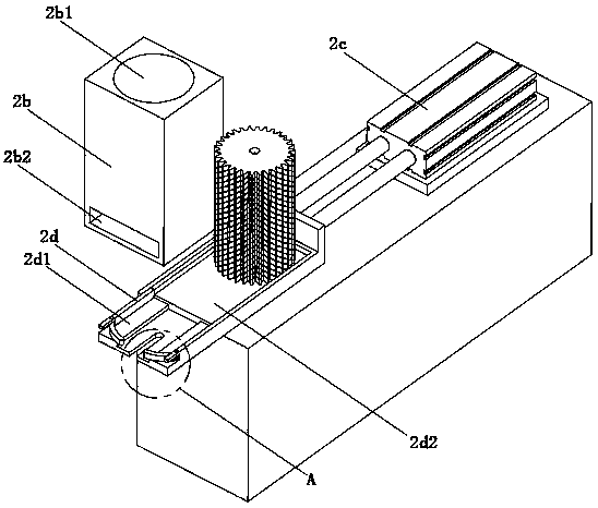
[0028] refer to Figure 1 to Figure 10 The shown gear double-sided chamfering device includes a conveying mechanism 1, a feeding mechanism 2, a processing mechanism 4 and a blanking mechanism 5, and the feeding mechanism 2, the processing mechanism 4 and the blanking mechanism 5 are arranged in a circle in sequence On the side of the conveying mechanism 1, the feeding mechanism 2 includes a mounting table 2a, a hopper 2b, a feeding cylinder 2c and a feeding plate 2d, the hopper 2b is in a rectangular structure and is vertically arranged on the upper end of the mounting table 2a, and the hopper The middle part of 2b is provided with a trough 2b1 for placing gears, and the bottom of the hopper 2b is provided with a feeding hole 2b2 for the feeding plate 2d to pass through. One end of the feeding plate 2d extends to th...


PUM


Abstract

The invention relates to the field of machinery machining, in particular to a double-face chamfering mechanism of a gear. The double-face chamfering mechanism comprises a conveying mechanism, a feeding mechanism, a machining mechanism and a discharge mechanism. The feeding mechanism comprises an installation table, a hopper, a feeding air cylinder and a feeding plate. The middle part of the hopperis provided with a material groove. The bottom of the hopper is equipped with a feeding hole allowing the feeding plate to penetrate. One end of the feeding plate extends towards the conveying mechanism and the other end of the feeding plate penetrates through the hopper to be fixedly connected with an output end of the feeding air cylinder. The feeding air cylinder is horizontally arranged on the installation table. The position where the feeding plate is close to the front half part of the conveying plate is provided with a first feeding groove. The position where the feeding plate is closeto the back half part of the feeding air cylinder is provided with a second feeding groove. The front part of the feeding plate is equipped with a U-shaped groove. The front end of the feeding plateis provided with two symmetrically-arranged limiting assemblies. Therefore, automatic feeding and locating operation are achieved during the gear chamfering process. Additionally, edges of upper and lower surfaces of the gear can be subjected to chamfering machining at the same time through a first chamfering assembly and a second chamfering assembly.

Description

technical field [0001] The invention relates to the field of machining, in particular to a gear double-sided chamfering mechanism. Background technique [0002] Gear is a kind of precision workpiece. With the development of technology, the requirements for gear are getting higher and higher, and gears often produce burrs in the process of machining and forming. These burrs are a major factor affecting the accuracy of gears. The burrs cause the gear to be scrapped, and the burr also makes the gear produce noise during use. Therefore, the edge of the gear needs to be chamfered during the processing of the gear, which can reduce the generation of burrs in the subsequent processing. However, the current general gear chamfering machine, Most of them require workers to cooperate with feeding, and the gears need to be fixed on the station by manual practical bolts. The operation is complicated and affects the processing speed. The gear chamfering work on some production lines usual...

Claims


Application Information

Patent Timeline
Patent Type & Authority Applications(China)
IPC IPC(8): B23F19/10B23F23/00B23Q7/00
CPCB23F19/10B23F23/00B23Q7/00
Inventor 金方明
Owner 金方明
Why Eureka
Try Eureka