Eureka AIR delivers breakthrough ideas for toughest innovation challenges, trusted by R&D personnel around the world.

Crankshaft pulley assembly

A crankshaft pulley and pulley technology, applied in the field of auto parts, can solve the problems of unstable speed of belt drive accessories, fluctuation of engine crankshaft speed, unstable speed, etc., to achieve simple structure, reduce output speed fluctuation, and belt output stability. Effect

Inactive Publication Date: 2018-05-11
SINO TRUK JINAN POWER
View PDF6 Cites 2 Cited by
  • Summary
  • Abstract
  • Description
  • Claims
  • Application Information

AI Technical Summary

Problems solved by technology

During the operation of the engine crankshaft, due to the specific working conditions of each cylinder taking turns to do work at a certain rotation angle, the engine crankshaft has torsional vibration and speed fluctuations during operation, which will cause the crankshaft pulley connected to the engine shaft to also There will be a phenomenon of unstable speed, which will cause the belt to slip, resulting in the occurrence of unstable speed of the belt drive accessories, etc.

Method used


Image

  • Crankshaft pulley assembly
  • Crankshaft pulley assembly
  • Crankshaft pulley assembly

Examples


Embodiment Construction

[0013] The present invention will be specifically described below in conjunction with the accompanying drawings and embodiments.

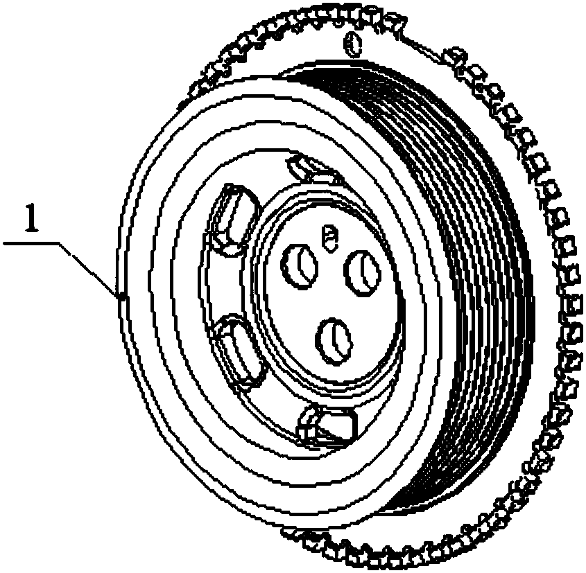
[0014] figure 1 Shown is the structural representation of the present invention.

[0015] The invention can reduce the torsion angle of the crankshaft of the engine, can read the rotational speed of the engine, allows a larger angular displacement between the pulley and the hub, and can make the belt output a more stable crankshaft pulley.

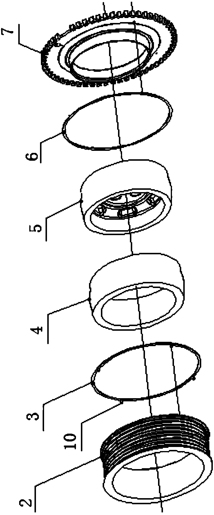
[0016] figure 2 Shown is an exploded schematic diagram of the present invention.

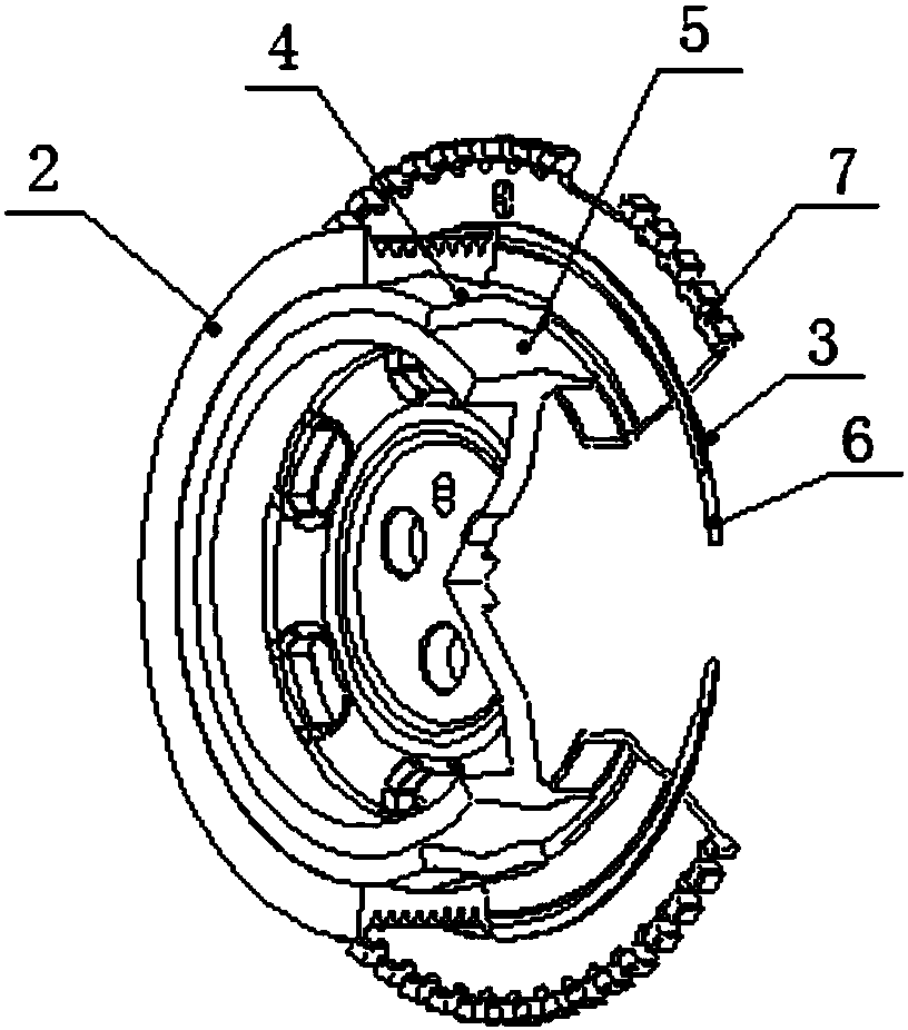
[0017] image 3 Shown is a schematic cutaway view of the belt pulley of the present invention.

[0018] The present invention comprises belt pulley 2, friction plate one 3, damping rubber 4, wheel hub 5, friction plate two 6 and signal disc 7.

[0019] Described signal disc 7 is provided with missing tooth 8 (as Figure 4 shown).

[0020] A signal disc 7 is pressed on the hub of the pulley 1, and the signal disc 7 with mi...


PUM


Abstract

The invention discloses a crankshaft pulley assembly. The crankshaft pulley assembly comprises a belt pulley, a first friction piece, damping rubber, a hub, a second friction piece and a signal disc.The belt pulley is connected with the hub through the damping rubber. The hub of the belt pulley is equipped with the signal disc in a press fitting manner. The signal disc is provided with a gap tooth. The signal disc with the gap tooth rotates in sync with a crankshaft in order to provide a rotating speed signal to an engine. The first friction piece and the second friction piece are installed between the belt pulley and the signal disc and respectively mounted on the belt pulley and the signal disc. With the crankshaft pulley assembly, the torsion angle of the engine crankshaft is reduced.The rotation speed of the engine can be read. Larger angular displacement is allowed between the belt pulley and the hub. Meanwhile, belt output is more stable. The crankshaft pulley assembly has features of simple structure and high product integration degree. In the meantime, the fluctuating output rotating speed of the belt pulley is reduced.

Description

technical field [0001] The invention relates to a crankshaft pulley assembly and belongs to the technical field of auto parts. Background technique [0002] The integration of various components on today's engines is getting higher and higher, and there are more and more accessories driven by belts, and those accessories driven by belts have stricter requirements on the stability of the rotational speed. During the operation of the engine crankshaft, due to the specific working conditions of each cylinder taking turns to do work at a certain rotation angle, the engine crankshaft has torsional vibration and speed fluctuations during operation, which will cause the crankshaft pulley connected to the engine shaft to also There will be a phenomenon of unstable speed, which will cause the belt to slip, resulting in the occurrence of unstable speed of the belt drive accessories. Contents of the invention [0003] The technical problem to be solved by the present invention is to...

Claims


Application Information

Patent Timeline
Patent Type & Authority Applications(China)
IPC IPC(8): F16H55/36F16H55/40F16F15/126
Inventor 孙晨郑康方凌云叶云展
Owner SINO TRUK JINAN POWER
Why Eureka
Eureka Blog
Learn More