Feed center discs in pulp or fiber refiners

A refiner and fiber technology, applied in pulp beating/refining methods, fiber raw materials, fiber raw material processing, etc., can solve the problems of pulp/fiber distribution influence, achieve uniform fiber quality, less feed change, less feed The effect of material conflict

Active Publication Date: 2019-07-23
VALMET OY
View PDF8 Cites 0 Cited by
  • Summary
  • Abstract
  • Description
  • Claims
  • Application Information

AI Technical Summary

Problems solved by technology

This can lead to material buildup in the middle of the rotor which can negatively affect pulp / fiber distribution

Method used


Image

  • Feed center discs in pulp or fiber refiners
  • Feed center discs in pulp or fiber refiners
  • Feed center discs in pulp or fiber refiners

Examples


Embodiment Construction

[0030] The present invention relates generally to refining of lignocellulose-containing material and more particularly to center disks for rotors in pulp or fiber refiners and pulp or fiber refiners having rotors comprising such center disks.

[0031] Throughout the figures, the same reference numerals are used for similar or corresponding elements.

[0032] As mentioned in the background section, there is a continuing need in the art to further improve pulp / fiber distribution in pulp / fiber refiners. Therefore, there is still a need for a feed center disc that further improves the pulp / fiber distribution in the refining zone of a pulp / fiber refiner.

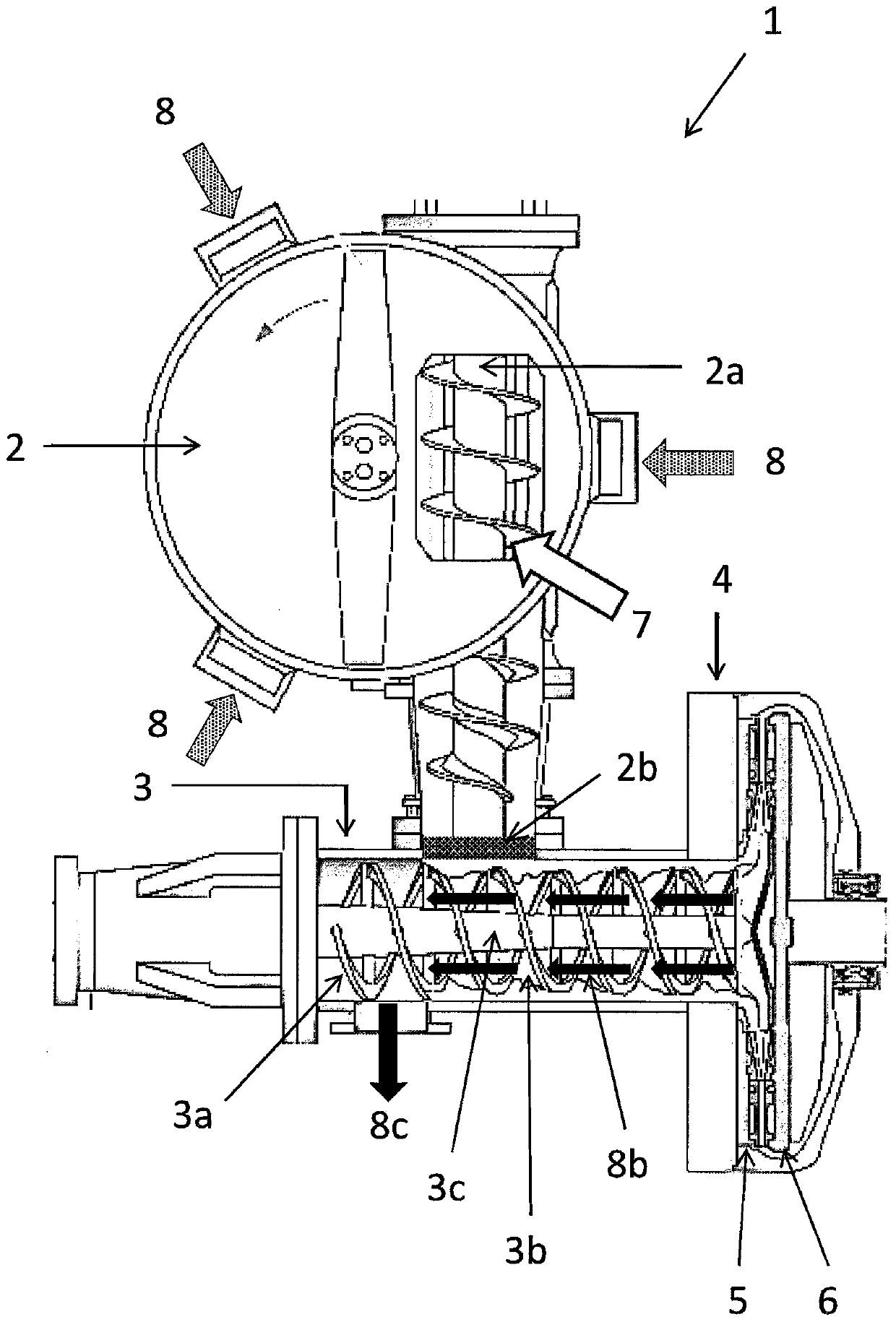
[0033] As mentioned above, figure 1 is a schematic diagram of a part of an embodiment of a pulp or fiber refiner 1 . Lignocellulose-containing material 7 such as wood chips is fed into the pre-heater 2 . Steam 8 is fed at the bottom of the preheater 2 and passed upwards through the chip pile. Chips are discharged from the pre...


PUM


Abstract

A central disk (10) for a rotor (6) in a pulp or fiber refiner (1), the central disk having a surface (200) provided with at least one feed wing (100), the at least one feed wing Lignocellulose-containing material (7) for directing flow onto the surface (200) towards the periphery of the central disc (10). The at least one feed wing (100) is an elongated protrusion arranged such that the second end (100b) of the feed wing (100) is arranged farther from the center of the central disk (10) than the first end (100a), And is also displaced relative to the first end portion (100a) in a direction opposite to the direction of rotation (11) of the rotor (6) and central disk (10). The at least one feed wing (100) is provided with at least one opening (101) which allows the steam (8b) to flow in a direction opposite to the direction of rotation (11) when the central disc (10) is rotated in the direction of rotation (11). The direction of the pointed component flows through the opening (101).

Description

technical field [0001] The present invention relates generally to refining of lignocellulose-containing material and more particularly to center disks for rotors in pulp or fiber refiners and pulp or fiber refiners having rotors comprising such center disks. Background technique [0002] A commonly used pulp or fiber refiner comprises a rotor unit and a stator unit (or alternatively two rotor units) aligned along a common axis and facing each other for grinding lignocellulose-containing material, such as wood chips, into pulp. Refining of the pulp / fiber takes place in the region of the rotor unit or the connection between the rotor and the stator unit or stator. figure 1 is a schematic diagram of a part of an embodiment of a pulp / fiber refiner 1 viewed from above. currently using figure 1 During the process of the pulp / fiber refiner 1, lignocellulose-containing material 7, such as wood chips, is fed into the pre-heater 2. Steam 8 is fed at the bottom of the preheater 2 an...

Claims


Application Information

Patent Timeline
Patent Type & Authority Patents(China)
IPC IPC(8): D21B1/14B02C7/12D21D1/30
CPCB02C7/12D21D1/30D21D1/306D21B1/14B02C7/06
Inventor T·林德布罗姆
Owner VALMET OY
Why Eureka
Try Eureka