Valve with guide vanes for coolant for internal combustion engines

A technology for guide vanes and cooling valves, applied in valve heating/cooling devices, internal combustion piston engines, combustion engines, etc.

Active Publication Date: 2020-01-24
FEDERAL MOGUL VALVETRAIN GMBH
View PDF5 Cites 0 Cited by
  • Summary
  • Abstract
  • Description
  • Claims
  • Application Information

AI Technical Summary

Problems solved by technology

[0004] However, in particular, there is still a need for further improvement of the cooling or cooling characteristics of the exhaust valves

Method used


Image

  • Valve with guide vanes for coolant for internal combustion engines
  • Valve with guide vanes for coolant for internal combustion engines
  • Valve with guide vanes for coolant for internal combustion engines

Examples


Embodiment Construction

[0036] In the specification and in the drawings, the same or similar reference numerals are used to refer to the same or similar parts and elements. In order to avoid an excessively long description, elements already described in one figure are not individually mentioned in another figure.

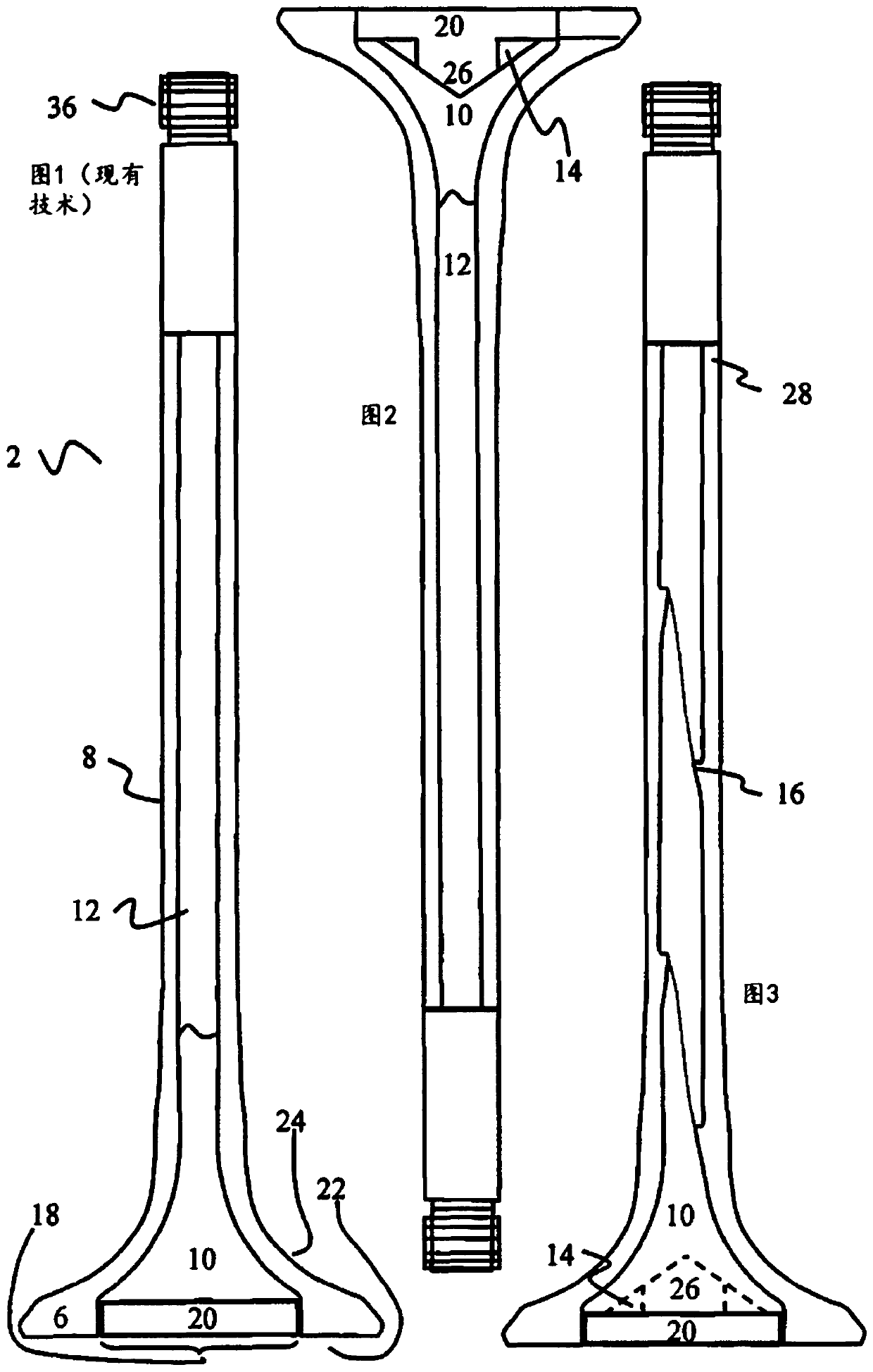
[0037] figure 1 A conventional internally cooled valve 2 is shown with a valve stem 8 , which terminates at a lower end in a valve disk 6 . The valve stem 8 ends at the top at a rod end 36 where the valve is normally controlled. The valve is internally provided with a cavity 10 filled with coolant 12 . Sodium, which is liquid at the operating temperature of the internal combustion engine, is usually used as a coolant. Typically, not the entire cavity, but only 2 / 3 to 3 / 4 of the cavity of the valve is filled with sodium. During operation, the sodium moves up and down in the valve stem 8 or in the cavity 10 of the valve stem 8 and in the process transports heat from the valve disk 6 in t...


PUM


Abstract

The invention relates to an internally cooled inlet valve or an internally cooled discharge valve (4) for an internal combustion engine, said internally cooled inlet valve or internally cooled discharge valve having a valve disc (6), a valve stem (8) and a Cavity (10) inside stem (8) and disc (6). A coolant (12) is arranged in a cavity (10), which cavity (10) is provided with at least one guide vane (14, 16) for the coolant (12).

Description

technical field [0001] The invention relates to cooling valves for internal combustion engines. More specifically, the present invention relates to a sodium cooled inlet or outlet valve for internal combustion engines provided with guide vanes in order to control or influence the movement of the sodium filling inside the valve. Background technique [0002] Internally cooled exhaust valves or sodium cooled exhaust valves have been known since 1935 at the latest. [0003] Sodium cooling and its effects are well known in the prior art, and technological developments in recent years have mainly involved increased coolant volumes in the area of ​​the valve disc and simplified manufacturing methods to enable more cost-effective manufacture of sodium-cooled valves . [0004] However, in particular, there is still a need for a further improvement of the cooling or cooling properties of the exhaust valve. Furthermore, there is a need to make available the most cooled cavity valve...

Claims


Application Information

Patent Timeline
Patent Type & Authority Patents(China)
IPC IPC(8): F01L3/14
CPCF01L3/10F01L3/14F01L2303/01F01L2301/00F01L2303/00F16K49/007
Inventor 迪尔克·朔贝尔斯蒂芬·凯勒曼吉多·贝亚德
Owner FEDERAL MOGUL VALVETRAIN GMBH
Why Eureka
Try Eureka