Rotor, rotating electrical machine provided therewith, and method of manufacturing rotor

A technology of a rotating electrical machine and a manufacturing method, which is applied in the manufacture of motor generators, stator/rotor bodies, and electric components, etc., can solve problems such as rotor damage and magnet damage, and achieve the effect of high productivity

Inactive Publication Date: 2018-05-11
HITACHI AUTOMOTIVE SYST LTD
View PDF5 Cites 3 Cited by
  • Summary
  • Abstract
  • Description
  • Claims
  • Application Information

AI Technical Summary

Problems solved by technology

When this stress is large, damage to the magnet or damage to the rotor may occur

Method used


Image

  • Rotor, rotating electrical machine provided therewith, and method of manufacturing rotor
  • Rotor, rotating electrical machine provided therewith, and method of manufacturing rotor
  • Rotor, rotating electrical machine provided therewith, and method of manufacturing rotor

Examples


Embodiment Construction

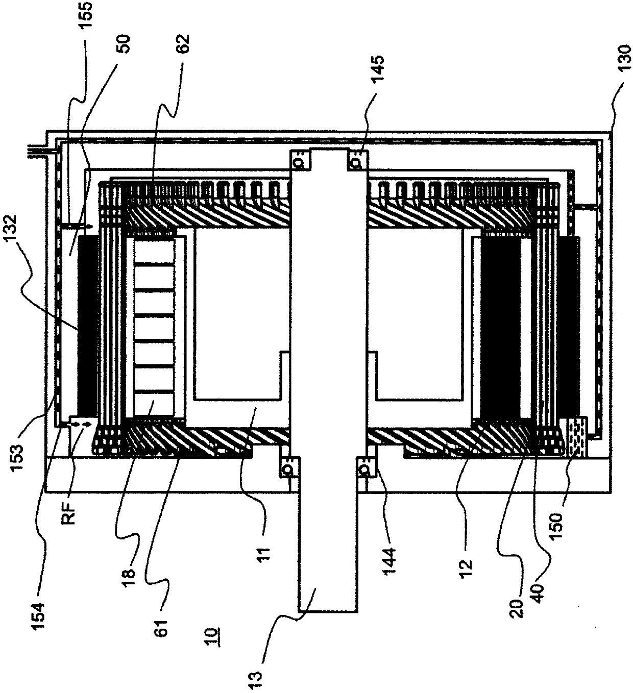
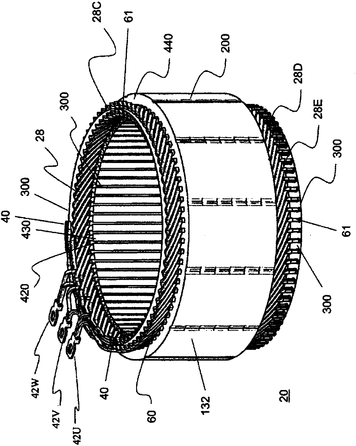
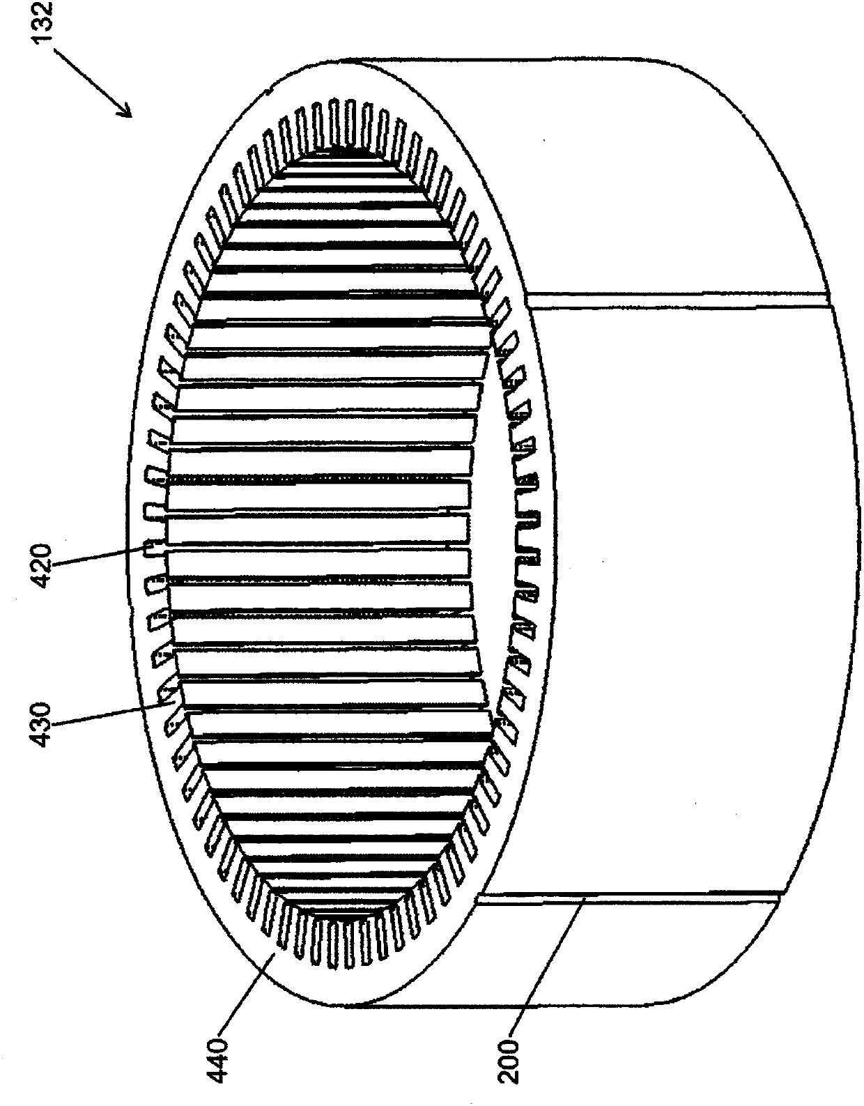
[0032] Embodiments of the present invention will be described below with reference to the drawings.

[0033] The rotary electric machine of this embodiment is a rotary electric machine suitable for running an automobile. Here, the so-called electric vehicles that use rotating electrical machines include hybrid electric vehicles (HEV) that are equipped with both an engine and a rotating electrical machine, and pure electric vehicles (EV) that run only on a rotating electrical machine without using an engine. The rotary electric machine can be used in two types, so here, in a representative manner, the description will be made based on the rotary electric machine used for a hybrid type vehicle.

[0034] In addition, in the following description, "axial direction" means the direction along the rotation axis of a rotary electric machine. The circumferential direction refers to a direction along the rotation direction of the rotary electric machine. The "radial direction" refers ...


PUM


Abstract

Provided are a rotor having good productivity, a rotating electrical machine provided therewith, and a method of manufacturing a rotor. The rotor for a rotating electrical machine is provided with a permanent magnet (18) and a rotor iron core (12) provided with a magnet insertion hole (810) into which the permanent magnet 18 is inserted, wherein a space between the permanent magnet (18) and the magnet insertion hole (810) is filled with a thermosetting powder resin (800). Further, according to the present invention, a method of manufacturing such a rotor for a rotating electrical machine is provided with: a first step of inserting the permanent magnet (18) and the thermosetting powder resin (800) into the magnet insertion hole (810); a second step of thermosetting the powder resin (800) while causing the rotor iron core (12) to rotate; and a third step of magnetizing the permanent magnet (18).

Description

technical field [0001] The present invention relates to a rotor, a rotating electrical machine equipped with the rotor, and a method of manufacturing the rotor. Background technique [0002] In a rotating electric machine, a rotating magnetic field is generated by supplying alternating current to a stator winding, and a rotor is rotated by the rotating magnetic field. In addition, it is also possible to convert mechanical energy applied to the rotor into electrical energy and output alternating current from the coil. Thus, there is a demand for high-speed rotation of permanent magnet type rotating electric machines used for driving electric vehicles such as hybrid vehicles (HV) and electric vehicles (EV). In particular, permanent magnet type rotating electrical machines that can achieve high output even in the high-speed rotation range are expected by the industry. For this reason, conventional permanent magnet rotating electric machines often use an embedded permanent mag...

Claims


Application Information

Patent Timeline
Patent Type & Authority Applications(China)
IPC IPC(8): H02K1/27H02K15/03
CPCH02K15/03H02K1/276H02K1/27H02K1/28H02K15/12
Inventor 中山健一山崎慎司福田知纮北原基男
Owner HITACHI AUTOMOTIVE SYST LTD
Why Eureka
Try Eureka