
Fluid mixing device

A fluid mixing and fluid mixture technology, which is applied in the directions of fluid mixers, mixers, transportation and packaging, etc., can solve the problem of difficulty in controlling the flow direction of fluid mixtures, and achieve the effect of reduced speed and easy direction control.

Inactive Publication Date: 2018-05-15
广东致密纳米技术有限公司
View PDF3 Cites 0 Cited by
  • Summary
  • Abstract
  • Description
  • Claims
  • Application Information

AI Technical Summary

Problems solved by technology

It is difficult to control the flow direction of the fluid mixture in the fluid mixing device due to the need to introduce high-speed flowing gas to meet the requirements of providing sufficient shear force

Method used


Image

  • Fluid mixing device
  • Fluid mixing device

Examples


Embodiment Construction

[0021] The following examples are used to illustrate the present invention, but are not intended to limit the scope of the present invention.

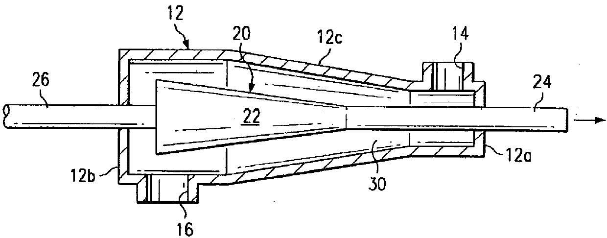
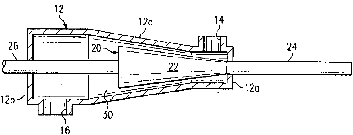
[0022] Such as figure 1 and 2 As shown, the fluid mixing device of the present invention includes a mixing shell 12 and a shear force applying device 20, the mixing shell includes a first cylindrical section 12a, a middle conical section 12c and a second cylindrical section 12b, the The first cylindrical section 12a, the middle conical section 12c and the second cylindrical section 12b are connected successively, the diameter of the first cylindrical section 12a is smaller than the diameter of the second cylindrical section 12b; the first cylindrical section 12a is provided with a fluid inlet 14 , the second cylindrical section 12b is provided with a fluid mixture outlet 16; the shear force applying device is arranged inside the mixing shell, and the shear force applying device includes a cone 22, and the cone One end of the cylindri...


PUM


Abstract

The invention discloses a fluid mixing device, which comprises a mixing shell and a shear force applying device. The mixing shell comprises a first cylindrical section, a middle conical section and asecond cylindrical section in sequential connection. The diameter of the first cylindrical section is smaller than that of the second cylindrical section, the first cylindrical section is provided with a fluid inlet, and the second cylindrical section is provided with a fluid mixture outlet. The shear force applying device is arranged in the mixing shell and comprises a conical barrel, one end ofthe conical barrel is connected with a cylindrical rod while the other end of the conical barrel is connected with a cylindrical shaft, one end of the cylindrical rod penetrates the first cylindricalsection to axially extend along the first cylindrical section, one end of the cylindrical shaft penetrates the second cylindrical section to axially extend along the second cylindrical section, and the cylindrical rod, the conical barrel and the cylindrical shaft are capable of moving leftwards and rightwards axially along the mixing shell.

Description

technical field [0001] The present invention relates to a fluid mixing device for mixing or reacting two or more fluids flowing in. Background technique [0002] Since the 1970s, fluid mixing devices (such as static mixers) have been applied in chemical industry, food industry, textile light industry and other industries, and have achieved good results. [0003] Static mixers are widely used in plastics, chemical industry, medicine, mining and metallurgy, food, daily chemical, pesticide, cable, petroleum, papermaking, chemical fiber, biology, environmental protection and other industries. Because the static mixer has low energy consumption, low investment, good effect and quick effect, it has brought considerable economic benefits to users. [0004] Static mixer is an advanced unit equipment. Unlike agitator, it has no moving parts inside. It mainly uses fluid flow and internal unit to realize the mixing of various fluids and the design rationality of special structure. Co...

Claims


Application Information

Patent Timeline
IPC IPC(8): B01F5/06
CPCB01F25/4413
Inventor 杨双林
Owner 广东致密纳米技术有限公司
Learn More