
Pipe reeling device used in electrostatic spraying equipment

A technology of electrostatic spraying and electrostatic spraying gun, which is applied in the field of pipeline coiling devices, can solve the problems of inconvenient handling of electrostatic spraying equipment, unstable hanging of electrostatic spraying guns, pedestrians being caught by pipelines, etc., and achieves the convenience of overall transportation, simple structure, avoid hanging effect

Active Publication Date: 2018-05-15
TIANCHANG JINLING ELECTRONICS
View PDF10 Cites 0 Cited by
  • Summary
  • Abstract
  • Description
  • Claims
  • Application Information

AI Technical Summary

Problems solved by technology

[0002] Electrostatic spraying uses the grounded object as the positive electrode, the paint atomization device as the negative electrode, and the paint atomization device is charged with a high negative voltage to form an electrostatic field between the two electrodes, so that the atomized paint particles are negatively charged, and the paint is sprayed. The spraying method that is effectively adsorbed on the object surface of the opposite electrode. The electrostatic spraying equipment mainly includes an electrostatic spray gun and a body. The electrostatic spray gun is mainly composed of a nozzle, a spray gun, an electrostatic generator, and a paint pump. The room is connected through the delivery pipeline so that the paint can be delivered to the electrostatic spray gun; in the idle state of the electrostatic spray gun, the electrostatic spray gun is generally hung on the machine body, and the delivery pipeline generally hangs on the ground at this time, and there is no positioning effect, thus It will cause inconvenience to the overall handling of the electrostatic spraying equipment, and passers-by are likely to be caught by the pipeline. At this time, a sudden pulling force will be generated on the electrostatic spray gun, causing it to fall to the ground, causing the electrostatic spray gun to fall on the body. Hanging is not stable

Method used


Image

  • Pipe reeling device used in electrostatic spraying equipment
  • Pipe reeling device used in electrostatic spraying equipment

Examples


Embodiment 1

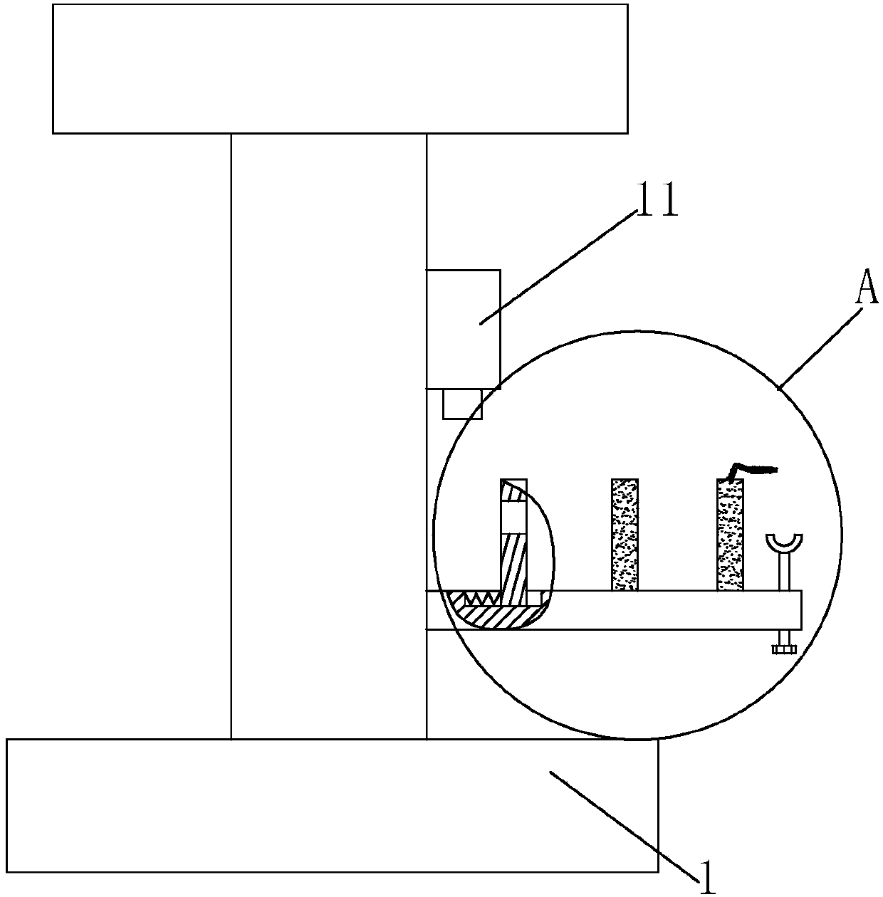
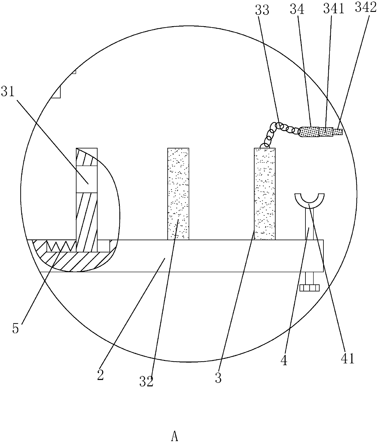
[0022] Embodiment 1: A kind of pipe coiling device used in electrostatic spraying equipment, such as figure 1 with 2 As shown, the electrostatic spraying equipment includes a machine body 1 and an electrostatic spray gun 11 suspended on the machine body 1. The pipe coiling device includes a working rod 2 fixedly arranged on the body 1 below the electrostatic spray gun 11 and perpendicular to the body 1. The working rod 2 is provided with a plurality of limiting plates 3 in the array along its length direction, and the limiting plates 3 are all slidably arranged on the working rod 2, and the positioning of the limiting plates 3 on the working rod 2 is realized by connecting the spring 5, and the limiting The position plate 3 is provided with a socket hole 31 for the pipeline to penetrate, and the end of the working rod 2 away from the body 1 is screwed with a support rod 4 parallel to the limit plate 3. The semicircle support frame 41.

specific Embodiment approach

[0023] Specific implementation method: firstly, the pipe is wound on the working rod 2 and between the limiting plate 3 and the working rod 2 close to the body 1. After the pipe is wound several times, its volume increases, which produces a certain squeeze on the limiting plate 3 Pressure effect, when the pipe is embedded compactly and firmly between this distance, one end of the pipe will go through the insertion hole 31 of the limiting plate 3, reach the second limiting plate 3, and connect the two limiting plates 3 to continue the winding work, in this way to achieve the winding of the pipe, when the pipe passes through the last limit plate 3, twist the support rod 4, so that the pipe is embedded in the semicircular support frame 41, and make the pipe There is a certain angle between the socket hole 31, at this time, it can effectively prevent the end of the pipe from slipping from the socket hole 31, effectively realize the positioning effect on the working rod 2 of the pip...

Embodiment 2

[0026] Embodiment 2: A pipe coiling device used in electrostatic spraying equipment, the difference from Embodiment 1 is that, as figure 2 As shown, at this moment, a hinge 33 is fixedly arranged on the limiting plate 3 away from the body 1, and a cylindrical plug body 34 is fixedly arranged at the end of the hinge 33 away from the limiting plate 3, and the outer peripheral surface of the cylindrical plug body 34 It is covered with a water-absorbing cotton layer 341 , and at the same time, a plurality of cylindrical plugs 342 are slipped and socketed in the cylindrical plug body 34 .

[0027] Specific embodiments: under the action of the cylindrical plug body 34, the port of the pipeline can be dust-proofed, that is, when the port of the pipeline passes through the insertion hole 31 of the last limiting plate 3 and is fixed in position, it can be The cylindrical plug body 34 is plugged into the port of the pipeline. At this time, under the action of the water-absorbing cotton...


PUM


Abstract

The invention discloses a pipe reeling device used in electrostatic spraying equipment. The electrostatic spraying equipment includes a machine body and an electrostatic spraying gun hung on the machine body; the pipe reeling device includes a work rod which is arranged on the machine body and positioned below the electrostatic spraying gun and is perpendicular to the machine body, multiple limiting plates are arranged in the length direction of the work rod in an arrayed mode, insertion holes for pipes to penetrate through are formed in all the limiting plates, the end, away from the machinebody, of the work rod is in threaded connection with supporting rods parallel to the limiting plates, and a semicircular supporting rack for the pipes to embed in is rotatably arranged on the supporting rods. By means of the pipe reeling device, a great limiting function can be achieved on the pipes on the machine body, no influences can be generated on pedestrians or the overall conveying effect,and the electrostatic spraying gun is convenient to hang stably on the machine body.

Description

technical field [0001] The invention relates to the field of electrostatic spraying equipment, in particular to a pipe coiling device used in the electrostatic spraying equipment. Background technique [0002] Electrostatic spraying uses the grounded object to be coated as the positive electrode, and the paint atomization device as the negative electrode, and the paint atomization device is charged with a high negative voltage to form an electrostatic field between the two electrodes, so that the atomized paint particles are negatively charged, and the paint is sprayed. The spraying method that is effectively adsorbed on the object surface of the opposite electrode. The electrostatic spraying equipment mainly includes an electrostatic spray gun and a body. The electrostatic spray gun is mainly composed of a nozzle, a spray gun, an electrostatic generator, and a paint pump. The room is connected through the delivery pipeline so that the paint can be delivered to the electrost...

Claims


Application Information

Patent Timeline
Patent Type & Authority Applications(China)
IPC IPC(8): B05B5/16B05B15/00
CPCB05B5/16B05B15/00
Inventor 茆文斌
Owner TIANCHANG JINLING ELECTRONICS
Learn More