
Heat source lifting mechanism for 3D printer line body consumable butt joint

A technology of 3D printers and consumables, applied in the direction of 3D object support structure, liquid material additive processing, additive processing, etc., can solve the problems of large environmental pollution, wasteful 3D printing consumables, and inability to realize multi-color printing, etc. Achieve the effect of realizing recycling, realizing multi-color printing, and solving the problem of single color

Active Publication Date: 2018-05-15
上海术字信息科技有限公司
View PDF8 Cites 1 Cited by
  • Summary
  • Abstract
  • Description
  • Claims
  • Application Information

AI Technical Summary

Problems solved by technology

[0002] At present, with the increasing popularity of 3D printing technology and its use in teaching, production, processing, and testing, 3D printers will have a small amount of redundant consumables during the printing process. This part of the consumables is not enough to support the next printing. For the rest of this part Consumables, the existing technology cannot recycle its raw materials, and can only be discarded, which makes 3D printing consumables wasteful and pollutes the environment; in addition, the existing ordinary 3D printers basically cannot realize multi-color printing of objects , but through special wiring equipment, this part of the vacancy can be made up. The specific operation is: calculate the length and sorting of the corresponding color consumables, connect multiple consumables in series through the special wiring equipment, and the concatenated multi-color consumables enter the 3D printer After that, the multi-color printing of the object can be completed in an orderly manner

Method used


Image

  • Heat source lifting mechanism for 3D printer line body consumable butt joint
  • Heat source lifting mechanism for 3D printer line body consumable butt joint
  • Heat source lifting mechanism for 3D printer line body consumable butt joint

Examples


Embodiment Construction

[0054] The technical solutions in the embodiments of the present invention will be clearly and completely described below in conjunction with the accompanying drawings in the embodiments of the present invention

[0055] It is obvious that the described embodiments are only a part of the embodiments of the present invention, but not all of them. Based on the embodiments of the present invention, all other embodiments obtained by persons of ordinary skill in the art without making creative efforts belong to the protection scope of the present invention.

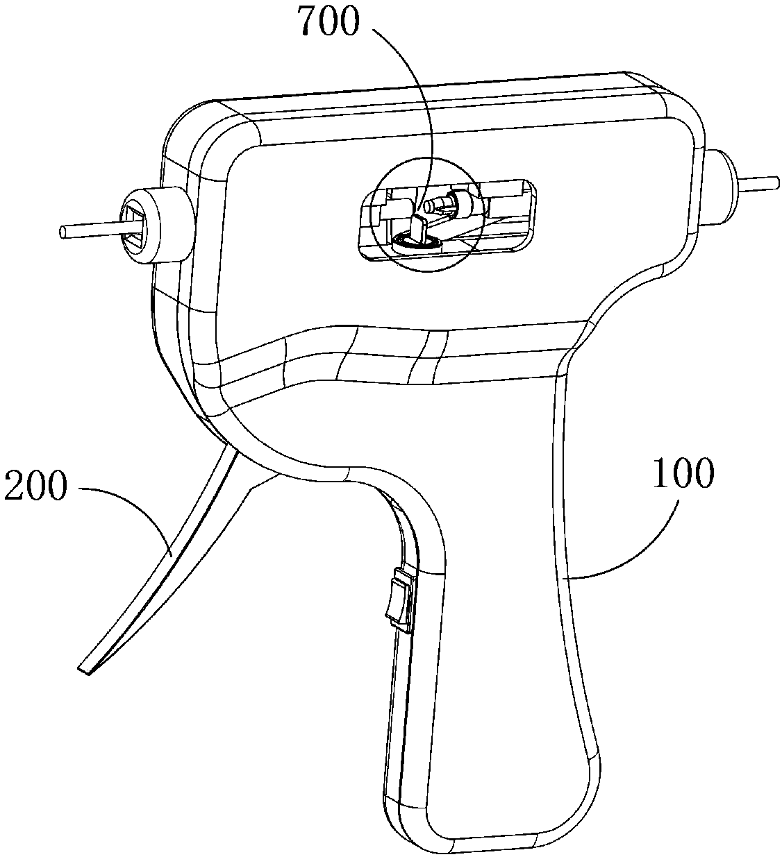
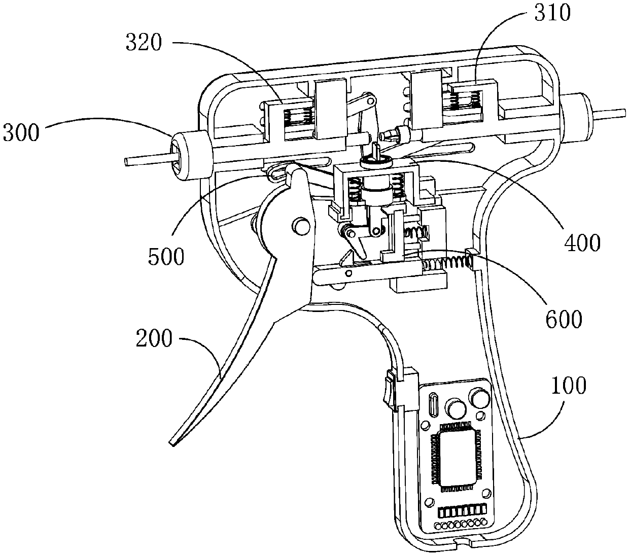
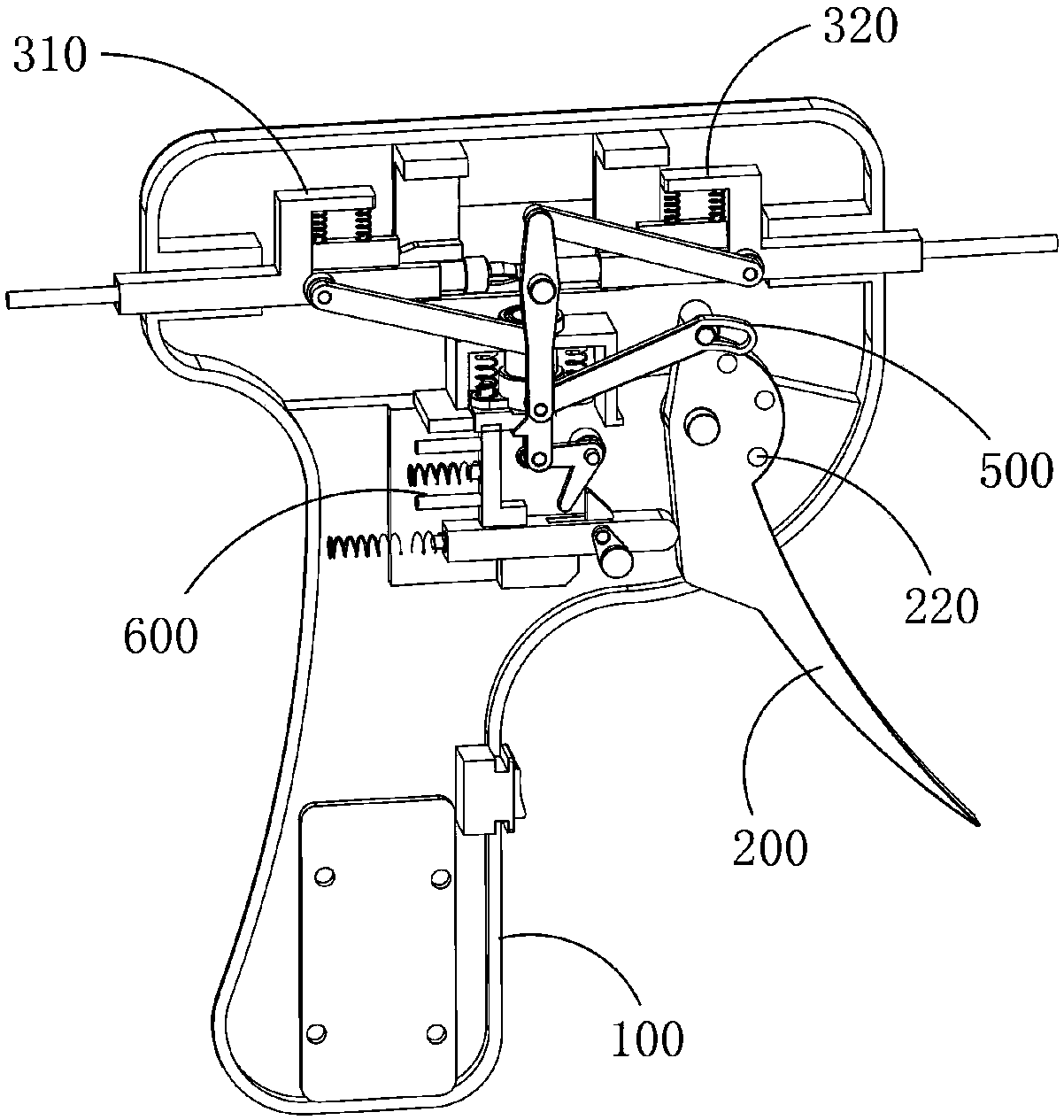
[0056] Such as Figure 1-17 As shown, the manual serial connection equipment for 3D printer wire consumables includes a housing 100, and a handle 200, a stringing device 300, a heating mechanism 400, a transmission mechanism 500, and a lifting mechanism 600 are installed in the housing 100.

[0057] The stringing device 300 includes a first stringing mechanism 310 and a second stringing mechanism 320, the first stringing mech...


PUM


Abstract

The invention provides a heat source lifting mechanism for 3D printer line body consumable butt joint. The heat source lifting mechanism comprises a shell. A handle, a heating mechanism and an elevator mechanism are installed inside the shell. The handle can generate pushing force in the moving process. The elevator mechanism receives the pushing force generated in the moving process of the handleand further drives the heating mechanism to ascend or descend under the effect of the pushing force. The heating mechanism is used for providing heat energy required by hot jointing for a hot jointing area. The handle is divided into three parts which include a handle part, a linkage part and a pushing part located between the handle part and the linkage part. The handle is hinged to the shell, and the hinged position of the handle and the shell is located between the linkage part and the pushing part. The core axis of a hinged shaft is perpendicular to conveying trails of consumables conveyed to the hot jointing area. The handle part is located outside the shell. The linkage part and the pushing part are located inside the shell and the pushing part makes contact with the elevator mechanism.

Description

technical field [0001] The invention relates to the technical field of 3D printers, in particular to a device for serially connecting consumables of 3D printers. Background technique [0002] At present, with the increasing popularity of 3D printing technology and its use in teaching, production, processing, and testing, 3D printers will have a small amount of redundant consumables during the printing process. This part of the consumables is not enough to support the next printing. For the rest of this part Consumables, the existing technology cannot recycle their raw materials, and can only be discarded, which makes 3D printing consumables wasteful and pollutes the environment; in addition, the existing ordinary 3D printers basically cannot realize multi-color printing of objects , but through special wiring equipment, this part of the vacancy can be made up. The specific operation is: calculate the length and sorting of the corresponding color consumables, connect multiple...

Claims


Application Information

Patent Timeline
Patent Type & Authority Applications(China)
IPC IPC(8): B29C64/106B29C64/336B29C64/314B33Y40/00
CPCB33Y40/00
Inventor 王和能
Owner 上海术字信息科技有限公司
Learn More