Cement retainer

A technology of retainer and cement, which is applied in wellbore/well components, earthwork drilling, sealing/isolation, etc., and can solve problems such as loss, wellbore blockage, and equipment damage

Pending Publication Date: 2018-05-15
VERTECHS OIL & GAS TECH CO LTD
View PDF13 Cites 4 Cited by
  • Summary
  • Abstract
  • Description
  • Claims
  • Application Information

AI Technical Summary

Problems solved by technology

[0005] (1) The technical problem to be solved by the present invention is: the existing cement retainer is easy to cause liquid to flow back during work, and th...

Method used


Image

  • Cement retainer
  • Cement retainer

Examples


Embodiment Construction

[0024] In order to understand the above-mentioned purpose, features and advantages of the present invention more clearly, the present invention will be further described in detail below in conjunction with the accompanying drawings and specific embodiments. It should be noted that, in the case of no conflict, the embodiments of the present application and the features in the embodiments can be combined with each other.

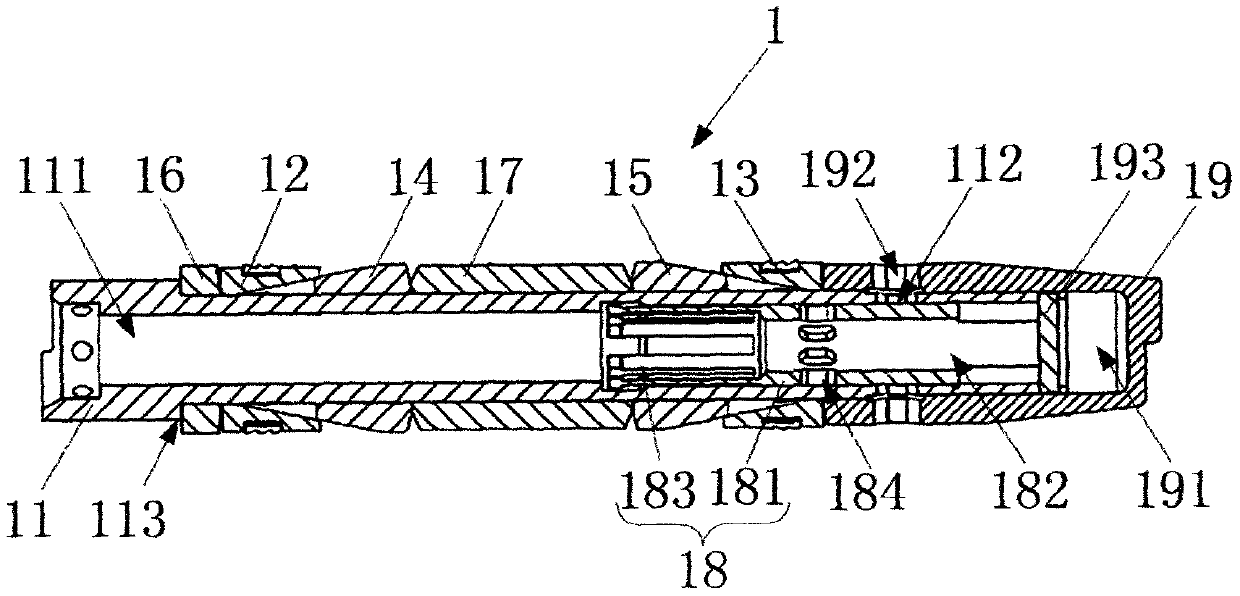
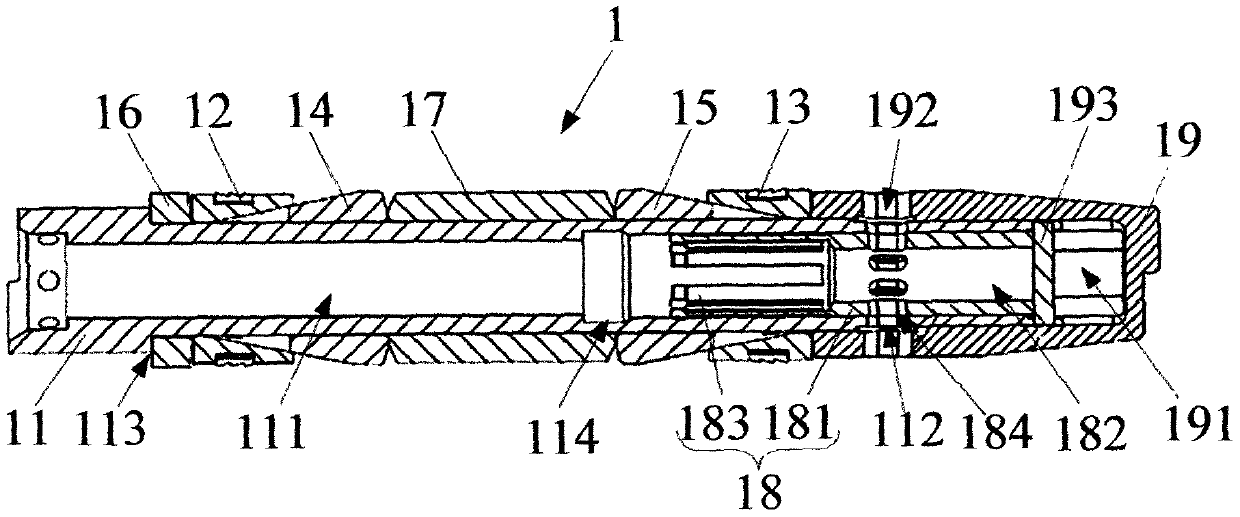
[0025] Such as figure 1 and figure 2 As shown, the present invention provides a cement retainer 1, comprising a first slip assembly 12, a center pipe 11, a lower joint 19, a second cone sleeve 15, a rubber sleeve 17 and an inner sliding sleeve 18, the center Both the pipe 11 and the lower joint 19 are tubular structures, the central pipe 11 forms a first hollow cavity 111 with two ends open inside, and the lower joint 19 forms a second hollow cavity 191 with one end open. One end of the central pipe 11 is inserted into the second hollow cavity 191 of the lo...


PUM


Abstract

The invention relates to the technical field of downhole tools, in particular to a cement retainer. The cement retainer includes a first slip assembly, a central pipe, a lower joint, a first conical sleeve, a rubber cylinder and an inner sliding sleeve; the cement retainer can be used with a conventional setting tool as a set, connected with the setting tool through an adapter and lowered to a designated position, and then setting is conducted by the setting tool; after setting is completed, the cement retainer is fixed at a predetermined setting depth in a shaft, a matched insertion pipe is placed downwards to push the inner sliding sleeve so that a third liquid passing hole can be communicated with a first liquid passing hole and a second liquid passing hole, then cement is injected intothe shaft through the three liquid passing holes, and plugging operation at a high-pressure water layer is completed; after the plugging operation is completed, the insertion pipe is unplugged and drawn back to drive the inner sliding sleeve move, the inner sliding sleeve moves to break the communication between the first liquid passing hole and the third liquid passing hole, and the problem of liquid backflow can be effectively avoided.

Description

technical field [0001] The invention relates to the technical field of downhole tools, in particular to a cement retainer. Background technique [0002] In the middle and late stage of oilfield development, due to the corrosion and perforation of the casing above the oil well cement return height, the cement cementing section leaks, causing the formation water in the oil layer adjacent to the high-pressure water layer to flow into the wellbore, or the energy of the oil layer drops adjacent to the high-pressure water layer and the oil layer. Water-bearing or water-flooded oil layers bring serious difficulties to oil field development. At present, some old oil wells that have been in production for many years have long-term high water content and are in the state of shutting down. Analysis and judgment: First, after long-term exploitation, the oil layer casing may be corroded and perforated, and casing leakage may cause oil layer water flooding; , forming a water head cone wi...

Claims


Application Information

Patent Timeline
IPC IPC(8): E21B33/13
CPCE21B33/13
Inventor 曾琦军
Owner VERTECHS OIL & GAS TECH CO LTD
Why Eureka
Try Eureka