Al technical title is built by PatSnap Al team. It summarizes the technical point description of the patent document.
A separation device and underwater machinery technology, applied in mechanical equipment, fixtures, etc., can solve the problems of polluted water, large impact load of structural parts, large separation noise, etc., and achieve the effect of avoiding misoperation
Inactive Publication Date: 2018-05-15
SHANXI UNIV
View PDF6 Cites 3 Cited by
Summary
Abstract
Description
Claims
Application Information
AI Technical Summary
This helps you quickly interpret patents by identifying the three key elements:
Problems solved by technology
Method used
Benefits of technology
Problems solved by technology
[0003] The purpose of the present invention is to solve the technical problems of the existing separation device such as one-time use, large impact load of structural parts, large separation noise and water pollution after the action, and provide an underwater machine that drives the mechanical mechanism to move by external water pressure Type Low Noise Separation Device
Method used
Image
Click on the blue label to locate the original text in one second.
Reading with bidirectional positioning of images and text.
Examples
Embodiment Construction
[0012] The present invention will be further described in detail below in conjunction with the accompanying drawings and specific embodiments.
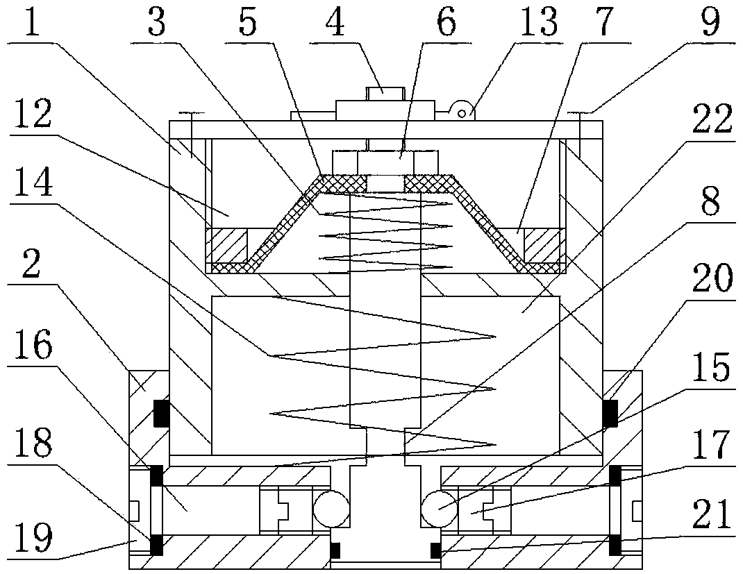
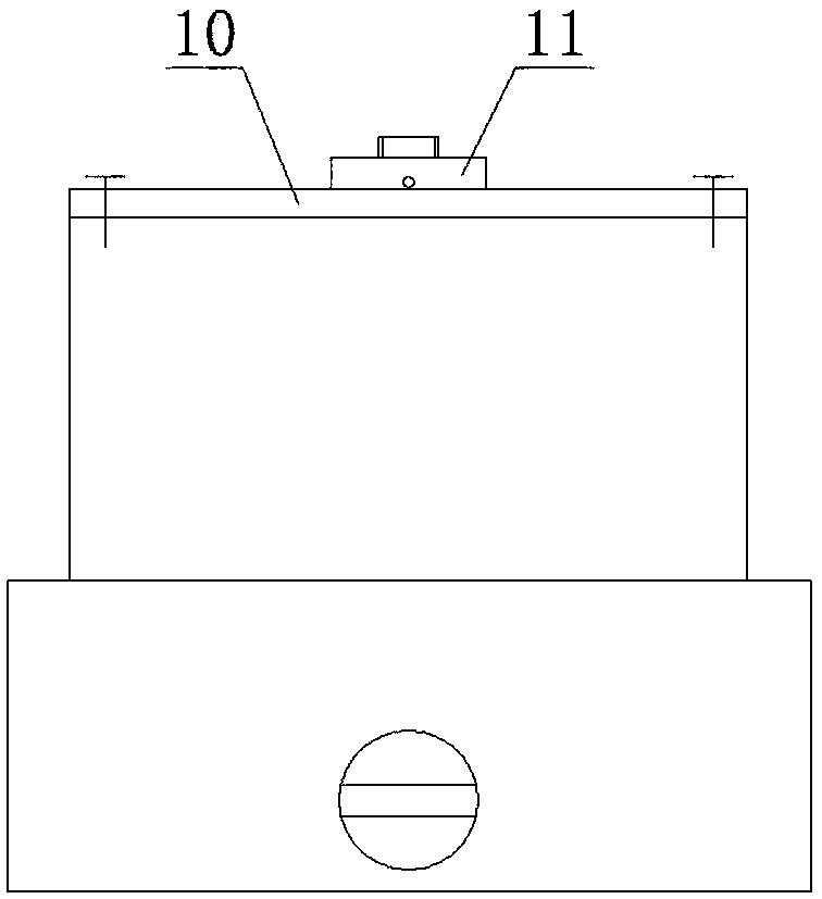
[0013] like figure 1 and figure 2 As shown, an underwater mechanical low-noise separation device in this embodiment includes an upper base 1, a lower base 2, a hydraulic spring 3, a hydraulic rod 4, a hydraulic membrane 5, a nut 6, and a pressure ring 7 , top cover 10, cylindrical platform 11, safety pin 13, separation spring 14, steel ball 15, screw plug 17, gasket 18, plug 19, large sealing ring 20 and small sealing ring 21, the hydraulic pressure rod 4 wears The round hole provided by the middle part of the inner cavity of the upper base body 1 is installed in the inner cavity of the upper base body 1; The upper surfaces of the partitions are in contact, and the middle hole is mounted on the shoulder provided on the upper part of the hydraulic rod 4 and pressed tightly with a nut 6; the hydraulic spring 3 is mounted on the hydra...
PUM
Abstract
The invention relates to an underwater mechanical low-noise separation device. The separating device mainly solves the problem that an existing separation device is disposable, the impact load of structural members is large, the separation noise is large, and water is polluted after action. According to the technical scheme, the underwater mechanical low-noise separation device comprises an upperbase body, a lower base body, a hydraulic pressure spring, a hydraulic pressure rod, a hydraulic pressure film, a nut, a compression ring, a top cover, a cylindrical table, a safety pin, a separationspring, steel balls, a plug screw, a sealing gasket, a plug, a large sealing ring and a small sealing ring, wherein the hydraulic pressure rod penetrates through a round hole formed in a middle partition plate in an inner cavity of the upper base body to be arranged in the inner cavity of the upper base body, the hydraulic pressure film is arranged in an upper cavity of the upper base body, and the outer edge of the hydraulic pressure film makes contact with the upper surface of the middle partition plate of the inner cavity of the upper base body. The underwater mechanical low-noise separation device has the advantages that the hydraulic pressure is used as the driving force, other power sources are not needed, the structure is simple, operation is convenient, and the specified water depth can be reached to relieve mechanical limiting so as to realize low-noise separation.
Description
technical field [0001] The invention relates to an underwater mechanical low-noise separation device, which belongs to the technical field of depth-fixed separation devices for underwater equipment. Background technique [0002] At present, separation technology is widely used in military and civilian fields, especially in the fields of aerospace, underwater weapons and underwater rescue. Common separation devices now mostly use pyrotechnics such as explosive bolts as the driving force. The pyrotechnic product is composed of an ignition element, a charge and a functional mechanism, and the energy of the explosive or combustion of the charge is used to drive the functional mechanism to complete the separation action. Although pyrotechnic products have the advantages of high reliability, high energy storage, fast action, and compact structure, they also have their own insurmountable shortcomings: one-time use, large impact load on structural parts, large separation noise, and...
Claims
Application Information
Patent Timeline
Application Date:The date an application was filed.
Publication Date:The date a patent or application was officially published.
First Publication Date:The earliest publication date of a patent with the same application number.
Issue Date:Publication date of the patent grant document.
PCT Entry Date:The Entry date of PCT National Phase.
Estimated Expiry Date:The statutory expiry date of a patent right according to the Patent Law, and it is the longest term of protection that the patent right can achieve without the termination of the patent right due to other reasons(Term extension factor has been taken into account ).
Invalid Date:Actual expiry date is based on effective date or publication date of legal transaction data of invalid patent.