Butterfly valve flow regulating device

A technology of flow regulating device and butterfly valve, which is applied in the direction of valve device, valve operation/release device, valve details, etc. It can solve the problems of poor flow limiting effect and achieve the effect of stable structure, precise water flow and precise control

Active Publication Date: 2018-05-15
ANHUI RONGDA VALVE
View PDF5 Cites 2 Cited by
  • Summary
  • Abstract
  • Description
  • Claims
  • Application Information

AI Technical Summary

Problems solved by technology

[0003] The purpose of the present invention is to solve the problem of poor flow limiting effect in the prior art, and propose a butterfly valve flow regulating device

Method used


Image

  • Butterfly valve flow regulating device
  • Butterfly valve flow regulating device
  • Butterfly valve flow regulating device

Examples


Embodiment 1

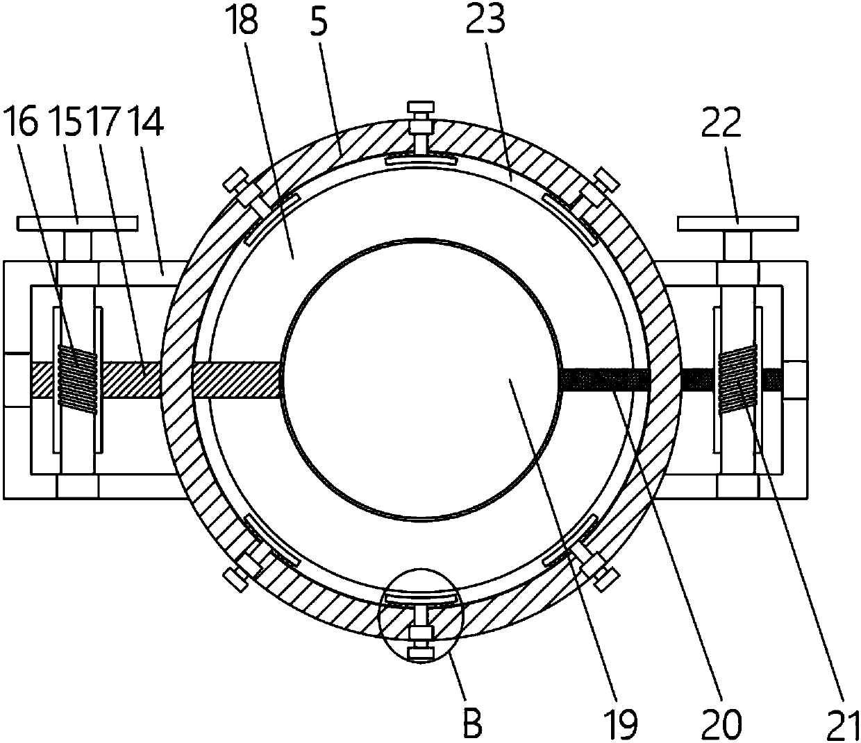
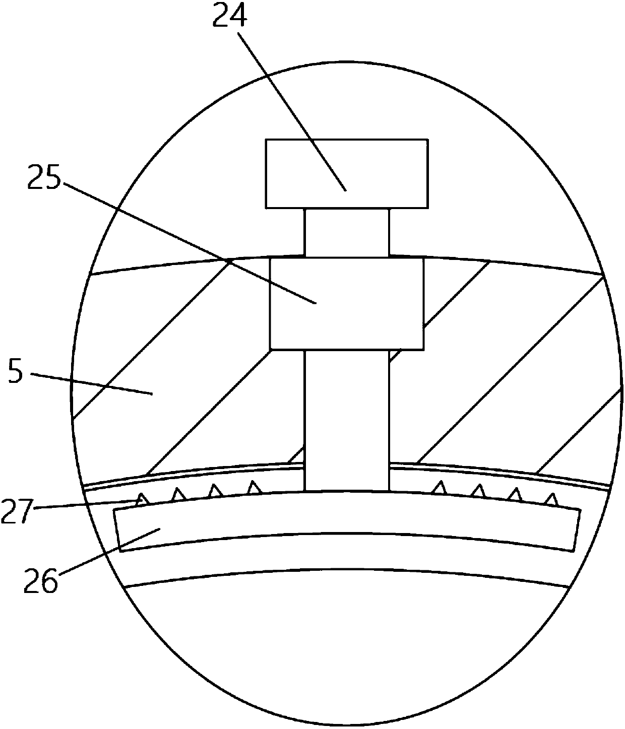
[0018] Embodiment 1: refer to Figure 1-2 , a butterfly valve flow regulating device, including a butterfly valve tube 5, a sealing rubber ring 23 is attached to the inner wall of the butterfly valve tube 5, and a plurality of engaging devices are attached around the sealing rubber ring 23, and the middle part of each engaging device Bolts 24 are all vertically rotated and connected, and a second nut 25 is installed on the inner wall of the butterfly valve pipe 5, and the bolt 24 is threadedly connected with the second nut 25, and an annular baffle 18 is installed in the butterfly valve pipe 5, and the hollow of the annular baffle 18 A circular baffle 19 is installed at the center, the left end of the annular baffle 18 is fixedly connected with a first rotating shaft 17, both ends of the butterfly valve tube 5 are fixedly connected with a valve body 14, the first rotating shaft 17 runs through the inner wall of the butterfly valve tube 5 and is rotatably connected On the inner...

Embodiment 2

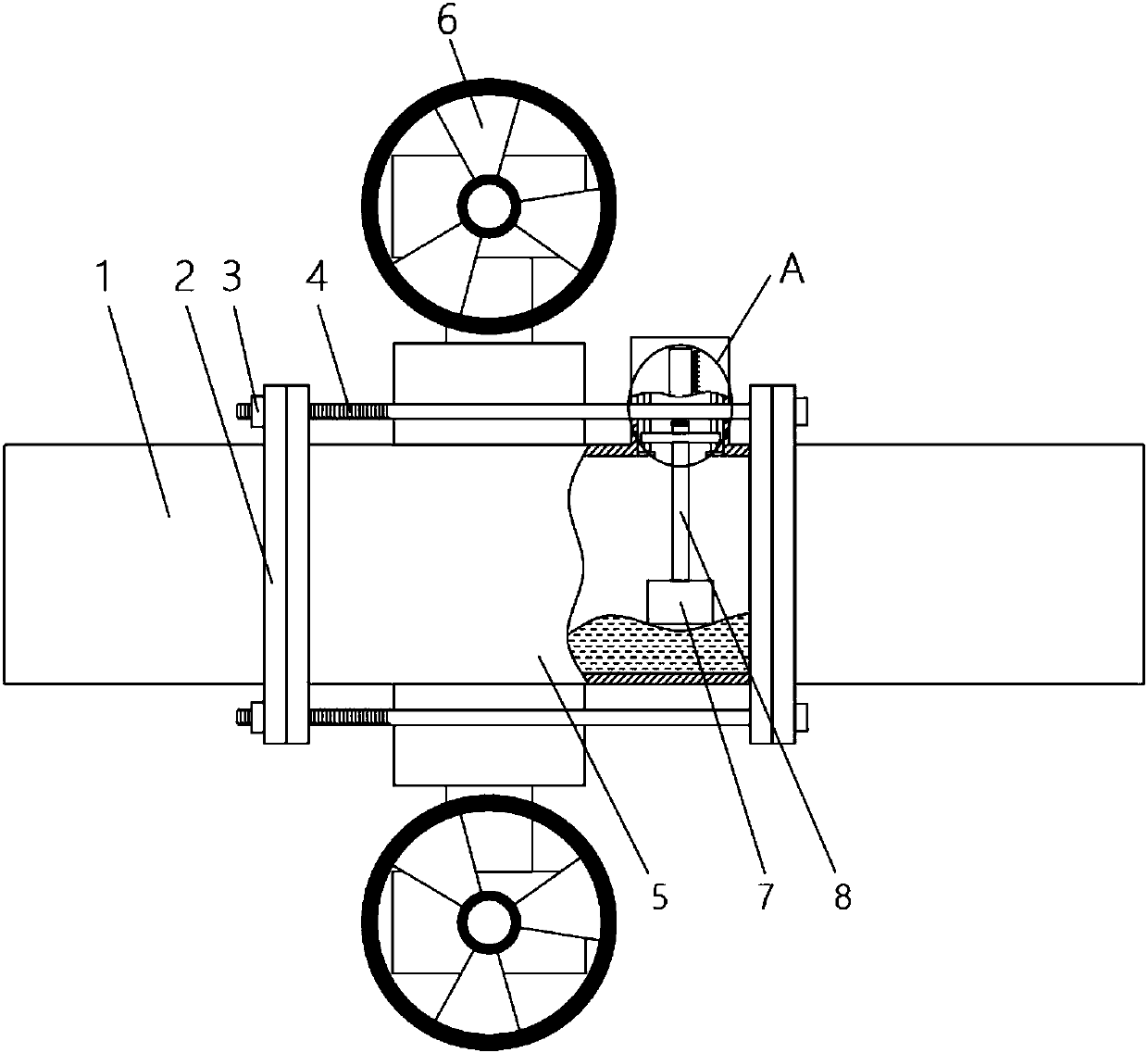
[0020] Embodiment 2: refer to Figure 1-4 , applying the present invention to a butterfly valve with current limiting and flow monitoring functions, including a butterfly valve pipe 5, both ends of the butterfly valve pipe 5 are connected to the water inlet pipe 1 through the flange 2, and the flanges 2 at both ends are jointly connected with screw rods 4. The left end of the screw rod 4 is threadedly connected with the first nut 3, and the upper end of the butterfly valve tube 5 is fixedly connected with a fixed block 9, and the fixed block 9 is provided with a display groove 10, and there are two symmetrical and vertical limit rods inside the fixed block 9 11, and the upper and lower ends of the limit rod 11 are all fixedly connected on the inner wall of the fixed block 9, the two limit rods 11 are jointly slidably connected with a slider 13, and the upper end of the slider 13 is fixedly connected with an indicating block 12, and the slide The middle part of the lower end of...


PUM


Abstract

The invention discloses a butterfly valve flow regulating device comprising a butterfly valve pipe. A seal rubber ring is attached to the inner wall of the butterfly valve pipe. A plurality of clamping devices are attached to the seal rubber ring in a surrounding mode. A bolt is connected in the middle of each clamping device vertically rotationally. A second nut is installed on the inner wall ofthe butterfly valve pipe, and the bolt is in threaded connection with the second nut. An annular stop piece is installed in the butterfly valve pipe. A round stop piece is installed in the hollow position of the annular stop piece. A first rotary shaft is fixedly connected to the left end of the annular stop piece. The two ends of the butterfly valve pipe are each fixedly connected with a valve body. The butterfly valve flow regulating device is stable in structure and convenient to operate, the designs of the two stop pieces are matched mutually so that water flow can be controlled more accurately, regulating use can be convenient for a worker, and the butterfly valve flow regulating device is worth popularization.

Description

technical field [0001] The invention relates to the technical field of butterfly valves, in particular to a butterfly valve flow regulating device. Background technique [0002] It is undeniable that butterfly valves have become one of the most widely used valves at present. Generally, a butterfly valve includes a valve body, a valve seat, a valve stem, and a valve disc. That is, the valve seat is fixed in the inner cavity of the valve, the valve disc is located in the inner cavity of the valve seat, and after the valve disc rotates, its edge and the valve seat are sealed or opened, and the valve rod is used to drive the valve disc to perform After rotating, the upper part of the valve stem passes through the upper part of the valve body and is connected to a rotating device such as a handle or an actuator. However, the working environment of butterfly valves is mostly harsh, such as dusty, high temperature, high pressure of the circulating medium, corrosive medium, etc., ...

Claims


Application Information

Patent Timeline
Patent Type & Authority Applications(China)
IPC IPC(8): F16K1/22F16K1/32F16K31/53F16K31/60
CPCF16K1/224F16K31/535F16K31/602
Inventor 胡启明
Owner ANHUI RONGDA VALVE
Why Eureka
Try Eureka