Spiral type oil separator

An oil separator and spiral technology, which is used in refrigeration components, refrigerators, lighting and heating equipment, etc., to achieve the effect of improving flow splitting efficiency, reasonable structure and reducing airflow velocity

Inactive Publication Date: 2018-05-15
XINCHANG HONGYU REFRIGERATION CO LTD
View PDF0 Cites 1 Cited by
  • Summary
  • Abstract
  • Description
  • Claims
  • Application Information

AI Technical Summary

Problems solved by technology

The existing spiral oil separator generally only separates the denser oil droplets in the exhaust gas on the side wall through the action of centrifugal force, and the single separation method has certain limitations

Method used


Image

  • Spiral type oil separator

Examples


Embodiment Construction

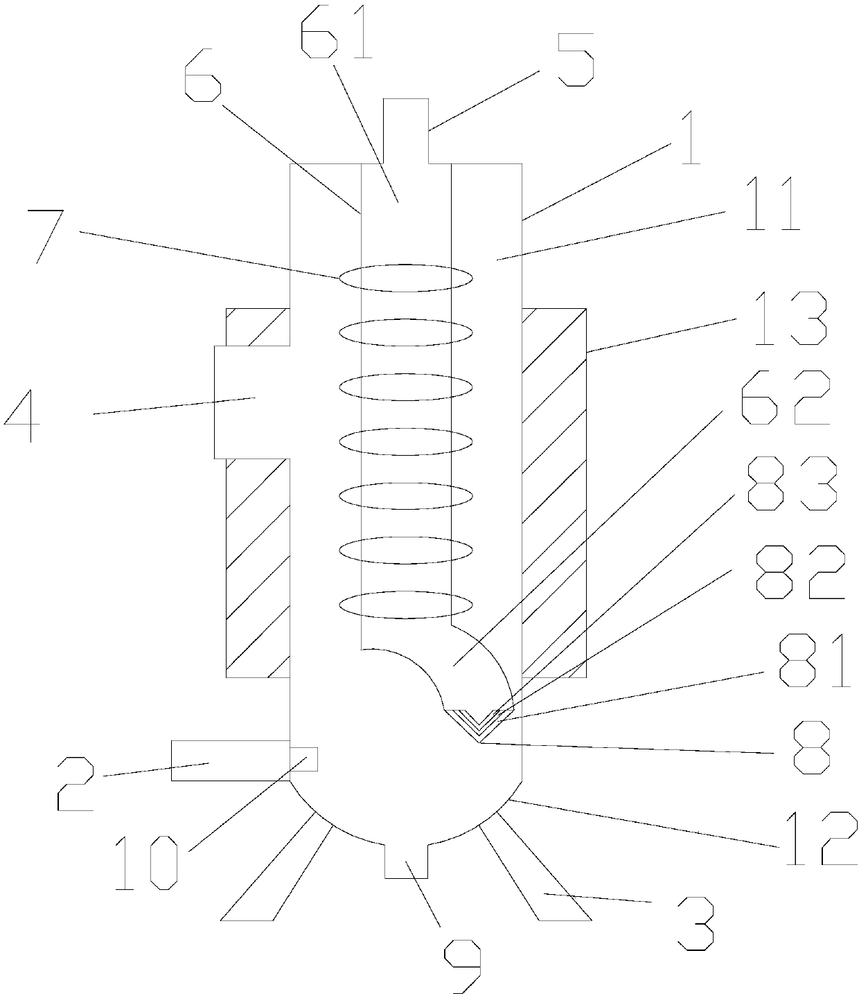
[0014] refer to figure 1 , the present invention provides a spiral oil separator, including a separation cylinder 1, an oil return pipe 2, a bracket 3, an air inlet pipe 4, an air outlet pipe 5, a separation cylinder 6, a spiral guide vane 7, a baffle plate 8, and a waste liquid outlet pipe 9. The separation cylinder 1 includes a cylindrical cylinder 11 and a bottom cover 12, the several brackets 3 are connected to the bottom cover 12 of the separation cylinder 1, and the brackets 3 and the bottom cover 12 are fixed together by welding. The inlet pipe 4 is installed on the side wall of the cylinder 11 of the separation cylinder 1, the outlet pipe 5 is installed on the top of the cylinder 11 of the separation cylinder 1, and the separation cylinder 6 is installed on the cylinder 11 of the separation cylinder 1 The inside of the separation cylinder 6 is connected to the top of the cylindrical cylinder 11, the outer wall of the separation cylinder 6 is fixed with a spiral guide v...


PUM


Abstract

The invention provides a spiral type oil separator which comprises a separation cylinder body, an oil return pipe, supports, an air inlet pipe, an air outlet pipe, a separation cylinder, a spiral guide blade, a baffle plate and a waste liquid educing pipe, wherein the separation cylinder body comprises a cylinder and a bottom cover; a plurality of supports are connected with the bottom cover of the separation cylinder body, and the supports are fixed to the bottom cover together in a welding mode; the air inlet pipe is arranged on the side wall of the cylinder of the separation cylinder body,and the air outlet pipe is arranged at the top of the cylinder of the separation cylinder body; the separation cylinder is arranged in the cylinder of the separation cylinder body and is connected with the top of the cylinder; the spiral guide blade is fixedly arranged on the outer wall of the separation cylinder, and the baffle plate is connected with the separation cylinder; the waste liquid educing pipe is arranged on the bottom cover of the separation cylinder. As the bent separation cylinder is adopted, the airflow direction can be changed. A water-cooled jacket is arranged on the outer wall of the separation cylinder body, and the baffle plate is added on the bottom of the separation cylinder, so that the airflow speed is reduced, and the separation effect is enhanced.

Description

【Technical field】 [0001] The invention relates to the technical field of structural components of refrigeration equipment, in particular to the technical field of a spiral oil separator. 【Background technique】 [0002] The function of the oil separator is to separate the lubricating oil in the high-pressure steam discharged from the refrigeration compressor to ensure the safe and efficient operation of the device. According to the oil separation principle of reducing the airflow speed and changing the airflow direction, the oil particles in the high-pressure steam It can be separated under the action of gravity. There are four types of oil separators commonly used: washing type, centrifugal type, packing type and filter type. The existing spiral oil separator generally only separates the denser oil droplets in the exhaust gas on the side wall through the action of centrifugal force, and the single separation method has certain limitations. 【Content of invention】 [0003] ...

Claims


Application Information

Patent Timeline
Patent Type & Authority Applications(China)
IPC IPC(8): F25B43/02
CPCF25B43/02
Inventor 石松
Owner XINCHANG HONGYU REFRIGERATION CO LTD
Why Eureka
Try Eureka