Inspection method, device, equipment and medium
A kind of equipment and technology to be tested, which is applied in the field of underground safety monitoring and wireless communication, can solve problems such as error-prone, and achieve the effect of improving accuracy and speed of determination
- Summary
- Abstract
- Description
- Claims
- Application Information
AI Technical Summary
Problems solved by technology
Method used
Image

Examples
Embodiment 1
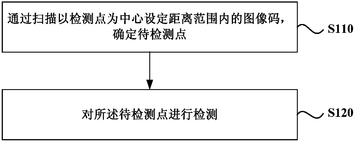
[0042] figure 1 It is a flow chart of an inspection method provided by Embodiment 1 of the present invention. This embodiment is applicable to the situation of performing patrol inspection on multiple detection points. The method can be executed by a patrol device, and the device can be realized by software and / or hardware. see figure 1 , an inspection method provided in this embodiment includes:
[0043] S110. Determine the point to be detected by scanning the image code within a set distance range centered on the detection point.
[0044] Wherein, the image code includes a barcode and / or a two-dimensional code. Wherein, the two-dimensional code may be a QR code, or another two-dimensional code in a custom format. With the development of technology, image codes may also include high-dimensional codes. This embodiment does not impose any limitation on this. Each detection point corresponds to an image code, and each image code pre-stores the information of its correspon...
Embodiment 2
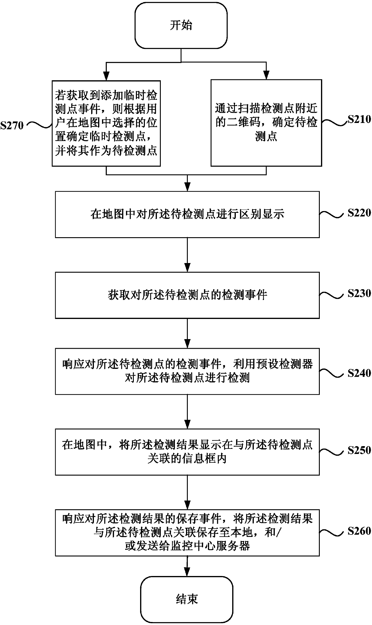
[0070] figure 2 It is a flowchart of an inspection method provided in Embodiment 2 of the present invention. This embodiment is based on the above-mentioned embodiments, and the application scenario is an application scenario in which an inspector conducts patrol inspections on downhole gas as an example. see figure 2 , the inspection method provided in this embodiment includes:
[0071] S210. Determine the point to be detected by scanning the two-dimensional code near the detection point.
[0072] S220. Differentially display the points to be detected on the map.
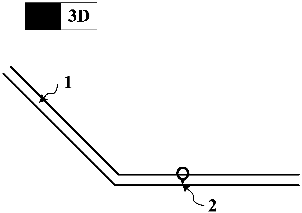
[0073] image 3 It is a partial schematic diagram of an underground traffic passage provided by Embodiment 2 of the present invention. see image 3 , the point 2 to be detected is set at a position of the channel 1 . Optionally, two-dimensional or three-dimensional display of the channel and the detection point may be performed by clicking a 2D button or a 3D button.
[0074] S230. Obtain a detection even...
Embodiment 3
[0087] Figure 6 It is a structural schematic diagram of an inspection device provided in Embodiment 3 of the present invention. see Figure 6 , the inspection device provided in this embodiment includes: a detection point determination module 10 and a detection module 20 .
[0088] Wherein, the detection point determination module 10 is used to determine the point to be detected by scanning the image code near the detection point;
[0089] The detection module 20 is configured to detect the points to be detected.
[0090] In the technical solution of the embodiment of the present invention, the point to be detected is determined by scanning the image code near the detection point, and then the detection of the detection point is realized. Compared with the method of manually selecting from a large number of detection points to determine the points to be detected, the method not only improves the speed of determining the points to be detected, but also improves the accuracy...
PUM
 Abstract
Description
Claims
Application Information