Over-voltage protection circuit

An overvoltage protection circuit and overvoltage protection technology, applied in the direction of overvoltage protection, parameter calibration/setting, etc., can solve the problems of fast response speed, poor voltage accuracy, and slow response speed of integrated chips

Active Publication Date: 2018-05-15
SHENZHEN MICROMULTICOPTER AERO TECH CO LTD
View PDF7 Cites 5 Cited by
  • Summary
  • Abstract
  • Description
  • Claims
  • Application Information

AI Technical Summary

Problems solved by technology

The integrated chip has a fast response rate and high voltage accuracy, but generally there is a range of voltage use, resulting in a small range of voltage use; and the solution of adding a Zener tube to a triode, although the voltage can be changed by adjusting the withstand voltage of the Zener tube and the triode The range of use, but the response rate is slow and the voltage accuracy is poor

Method used


Image

  • Over-voltage protection circuit
  • Over-voltage protection circuit

Examples


Embodiment Construction

[0020] In order to facilitate the understanding of the present invention, the invention will be described more fully below with reference to the associated drawings. A preferred embodiment of the invention is shown in the drawings. However, the present invention can be embodied in many different forms and is not limited to the embodiments described herein. Rather, these embodiments are provided so that the disclosure of the present invention will be thorough and complete.

[0021] Unless otherwise defined, all technical and scientific terms used herein have the same meaning as commonly understood by one of ordinary skill in the technical field of the invention. The terms used herein in the description of the present invention are for the purpose of describing specific embodiments only, and are not intended to limit the present invention. As used herein, the term "and / or" includes any and all combinations of one or more of the associated listed items.

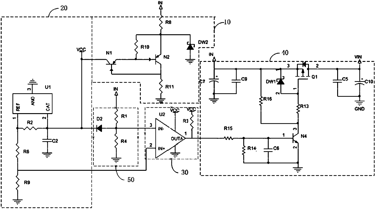
[0022] figure 1 is a...


PUM


Abstract

The invention relates to an over-voltage protection circuit. The circuit comprises a constant-current protection module, a reference voltage module, a comparison module, and an on / off control module.The first input end of the comparison module is connected with an input power supply. The input end of the constant-current protection module is connected with the input power supply. The output end of the constant-current protection module is connected with the input end of the reference voltage module. The output end of the reference voltage module is connected with the second input end of the comparison module. The output end of the comparison module is connected with the controlled end of the on-off control module. The on-off control module controls whether the input power supply suppliespower to a load circuit or not. The constant-current protection module is used for carrying out the constant-current power supply on the reference voltage module and performing the over-voltage protection on the reference voltage module. The reference voltage module is used for providing a stable reference voltage for the second input end of the comparison module. The comparison module is used forcomparing a voltage input by the first input end with the reference voltage, and then outputting a control signal for controlling the on-off state of the on / off control module. The over-voltage protection circuit is wide in voltage application range, fast in response speed and high in voltage precision.

Description

technical field [0001] The invention relates to the field of voltage overvoltage protection, in particular to an overvoltage protection circuit. Background technique [0002] If the input voltage is too high in the circuit, the internal components of the load circuit will be damaged or even burned, so an overvoltage protection circuit is needed to protect the circuit. There are two main schemes for the traditional overvoltage protection circuit: the scheme using integrated chips and the scheme using Zener tube plus triode. The integrated chip has a fast response rate and high voltage accuracy, but generally there is a range of voltage use, resulting in a small range of voltage use; and the solution of adding a Zener tube to a triode, although the voltage can be changed by adjusting the withstand voltage of the Zener tube and the triode Use range, but the reaction rate is slow and the voltage accuracy is poor. Contents of the invention [0003] Based on this, it is necess...

Claims


Application Information

Patent Timeline
Patent Type & Authority Applications(China)
IPC IPC(8): H02H3/20
CPCH02H3/006H02H3/20
Inventor 车嘉兴赖星卢致辉陈金颖苏忠可
Owner SHENZHEN MICROMULTICOPTER AERO TECH CO LTD
Why Eureka
Try Eureka