Steel bar bending device

A bending device and a technology for steel bars, applied in the field of steel bar processing, can solve the problems of reduced bending quality of steel bars, affecting the bending effect, twisting of both ends of steel bars, etc., to prevent steel bars from moving, ensuring bending quality, and preventing steel bars from rotating Effect

Inactive Publication Date: 2018-05-18
艾里芸(重庆)品牌营销策划有限公司
View PDF5 Cites 0 Cited by
  • Summary
  • Abstract
  • Description
  • Claims
  • Application Information

AI Technical Summary

Problems solved by technology

The traditional bending method is manual bending, but the labor intensity is high and the efficiency is low. Manual bending can only be seen in some places where the demand for bent steel bars is small; in order to reduce labor intensity and improve processing efficiency , the current bending of steel bars usually adopts mechanical bending to meet the large demand for bent steel bars
However, when bending one end of the steel

Method used


Image

  • Steel bar bending device

Examples


Embodiment Construction

[0012] The present invention will be described in further detail below by means of specific embodiments:

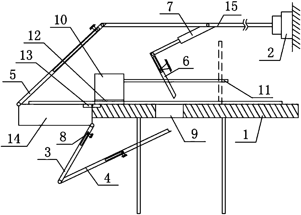
[0013] The reference signs in the drawings of the description include: support platform 1, cylinder 2, first connecting rod 3, second connecting rod 4, third connecting rod 5, fourth connecting rod 6, telescopic rod 7, pin 8, hole 9 , Bending seat 10, positioning rod 11, opening 12, hinge 13, bending plate 14, support rod 15.

[0014] Such as figure 1 A steel bar bending device shown includes a supporting platform 1, a cylinder 2, a first connecting rod 3, a second connecting rod 4, a third connecting rod 5, a fourth connecting rod 6, a telescopic rod 7 and four pins 8 . There is a hole 9 on the support platform 1, and the hole 9 runs through the support platform 1; the left end of the support platform 1 is fixed with a bending seat 10, and two positioning rods 11 are welded on the right side of the bending seat 10, and the two positioning rods 11 are parallel to each o...


PUM


Abstract

The invention relates to the field of steel bar processing, in particular to a steel bar bending device. The steel bar bending device comprises a rack and a supporting table. A hole is formed in the supporting table. The supporting table is fixedly provided with a bending seat. The bending seat is fixedly provided with two positioning rods which are parallel to each other and located on the same plane. A bending plate is hinged to the end, close to the bending seat, of the supporting table. A pin nail is fixed to the rack and slidably connected with a first connecting rod, a second connectingrod, a third connecting rod and a fourth connecting rod. One end of the first connecting rod is hinged to the bending plate. The other end of the first connecting rod is hinged to one end of the second connecting rod. The other end of the second connecting rod is provided with a clamping clip. The free end of an output shaft of an air cylinder is hinged to one end of the third connecting rod. Theother end of the third connecting rod is hinged to the bending plate. One end of a telescopic rod is hinged to the output shaft of the air cylinder. The other end of the telescopic rod is hinged to one end of the fourth connecting rod. The other end of the fourth connecting rod is provided with a clamping clip. When the technical scheme is adopted, the situation of different planes of the bendingend of a steel bar during bending is effectively prevented, and the bending quality is ensured.

Description

technical field [0001] The invention relates to the field of steel bar processing, in particular to a steel bar bending device. Background technique [0002] Steel bars are widely used in urban construction, traffic construction and other fields, and steel bars need to be bent for use. The traditional bending method is manual bending, but the labor intensity is high and the efficiency is low. Manual bending can only be seen in some places where the demand for bent steel bars is small; in order to reduce labor intensity and improve processing efficiency , the current bending of steel bars usually adopts mechanical bending to meet the large demand for bent steel bars. However, when bending one end of the steel bar, the other end of the steel bar will shake, which will affect the bending effect; at the same time, after bending one end of the steel bar, when bending the other end of the steel bar, it is easy to cause the bending end and the bent end One end of the bend is not ...

Claims


Application Information

Patent Timeline
IPC IPC(8): B21F1/00
CPCB21F1/00
Inventor 廖洪平
Owner 艾里芸(重庆)品牌营销策划有限公司
Why Eureka
Try Eureka