Steel plate grinding device with automatic compressing function

A functional, steel plate technology, applied in the field of steel plate grinding devices, can solve the problems that the grinding effect is difficult to achieve the expected effect, does not have a dust removal mechanism, and is troublesome to handle iron filings, and achieves the effects of novel design, long service life and labor saving.

Inactive Publication Date: 2018-05-18
长沙双合盛企业管理有限公司
View PDF8 Cites 20 Cited by
  • Summary
  • Abstract
  • Description
  • Claims
  • Application Information

AI Technical Summary

Problems solved by technology

During the production process of the steel plate, due to the long-term storage, the surface of the steel plate is prone to rust when it is in contact with external water vapor. When using the steel plate, it is necessary to polish the rust on the surface to ensure the normal processing of the steel plate; During the process, due to the rough surface of the steel plate after processing, a large number of burrs are generated. Usually, the processed surface needs to be polished. The existing grinding operation requires workers to hold the grinder and manually grind. The grinding efficiency is low, and the grinding effect is difficult to achieve. The expected effect is that the general grinding device needs to be manually fixed by the clamping device before grinding. The clamping process is time-consuming and the work efficiency is low. Moreover, the existing grinding device does not have a dust removal mechanism, and the scattered iron filings are troublesome to deal with, causing environmental pollution. Pollution

Method used


Image

  • Steel plate grinding device with automatic compressing function
  • Steel plate grinding device with automatic compressing function
  • Steel plate grinding device with automatic compressing function

Examples


Embodiment Construction

[0019] The following will clearly and completely describe the technical solutions in the embodiments of the present invention with reference to the accompanying drawings in the embodiments of the present invention. Obviously, the described embodiments are only some, not all, embodiments of the present invention. Based on the embodiments of the present invention, all other embodiments obtained by persons of ordinary skill in the art without making creative efforts belong to the protection scope of the present invention.

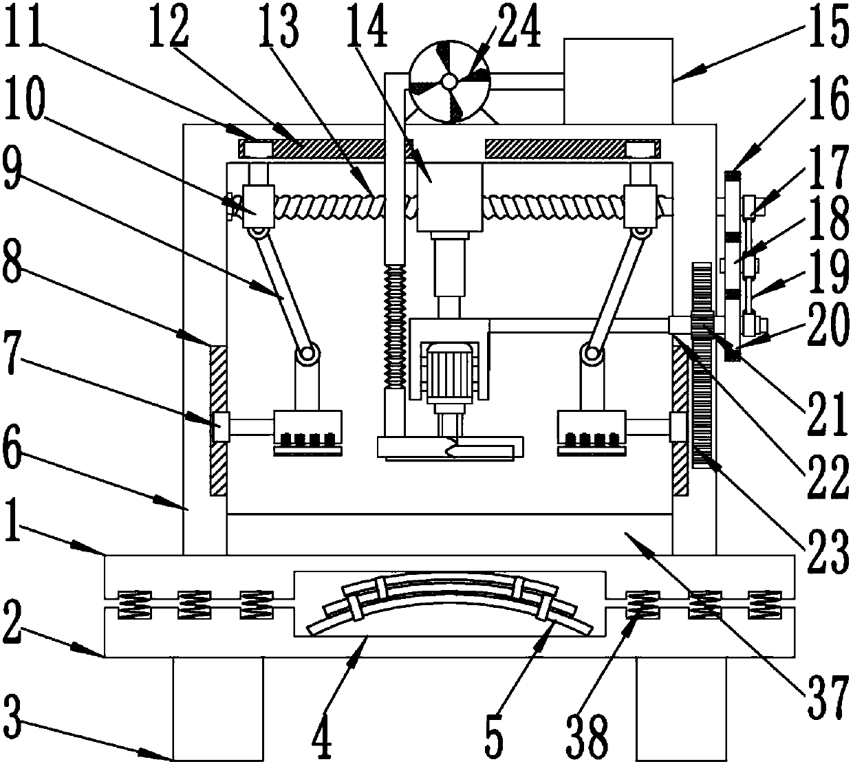
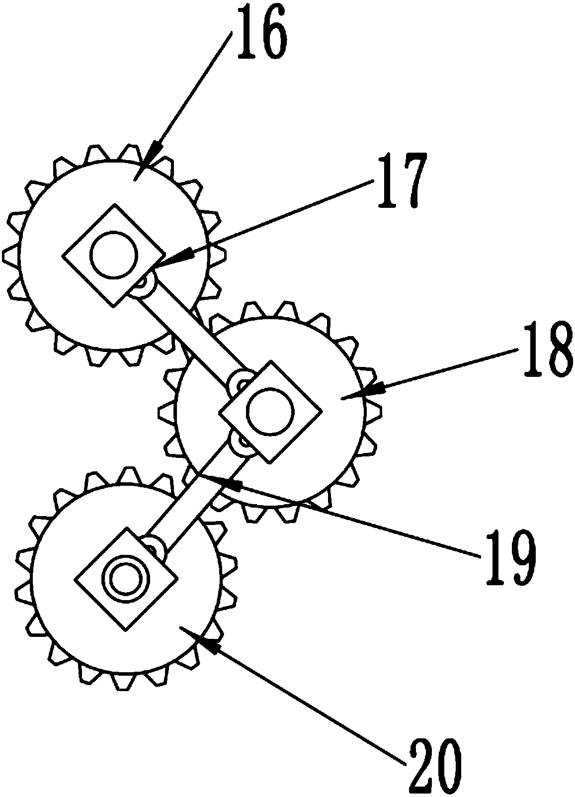
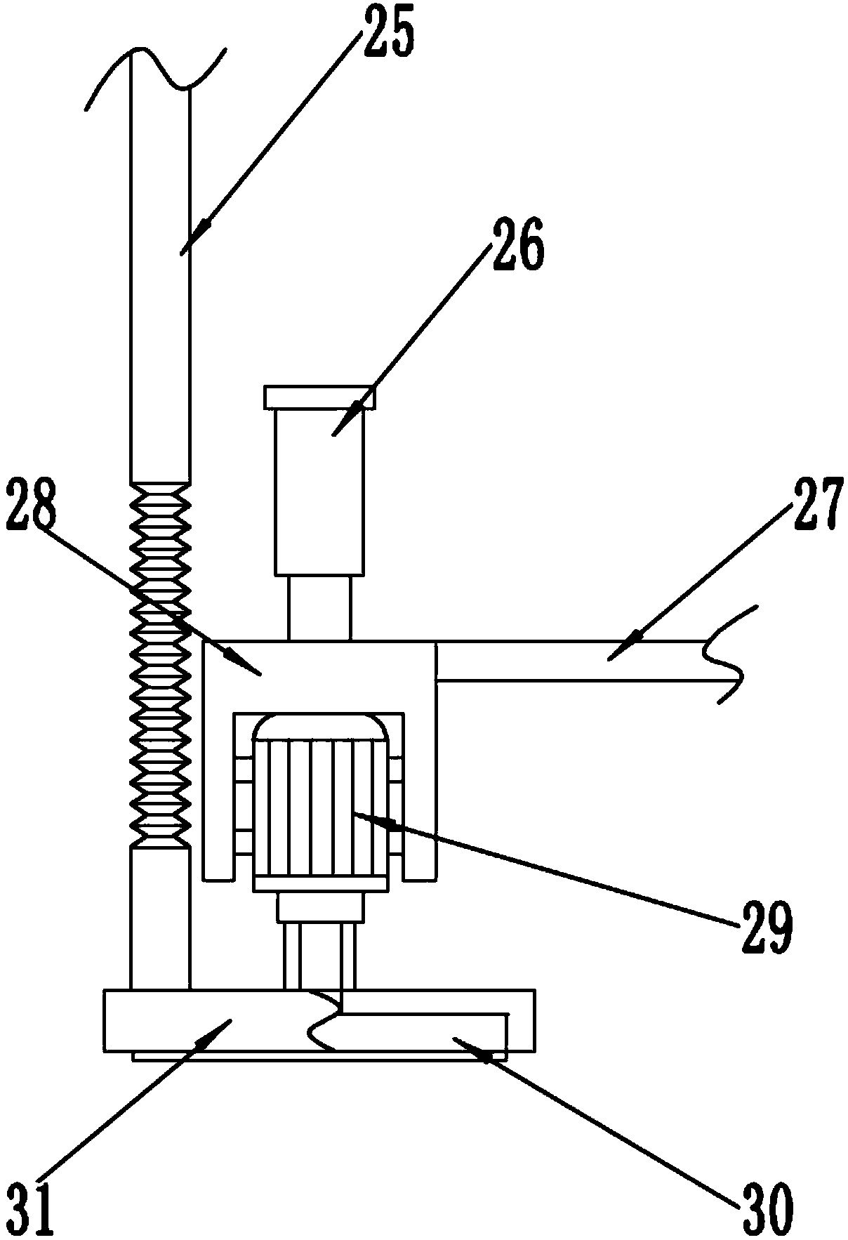
[0020] see Figure 1~4 , a steel plate grinding device with automatic pressing function, comprising an upper base plate 1, a lower base plate 2, a bracket 6, a grinding mechanism, a pressing mechanism and a dust removal mechanism; the bracket 6 is fixedly installed on the upper end of the upper base plate 1, and the upper base plate The upper end of 1 is also provided with a grinding table 37, the grinding table 37 is located inside the bracket 6, the lower ba...


PUM


Abstract

The invention discloses a steel plate grinding device with an automatic compressing function. The steel plate grinding device with the automatic compressing function comprises an upper bottom plate, alower bottom plate, a support, a grinding mechanism, a compressing mechanism and a dust removing mechanism; a fixing block is fixedly installed at the lower end of a horizontal cross rod of the support; the grinding mechanism is arranged at the lower end of the fixing block, and comprises a hydraulic telescopic rod, a U-shaped plate, a grinding motor and a grinding disk; the compressing mechanismcomprises a slider, a sliding groove, a pushing rod, a supporting rod, an upper fixing plate, a lower fixing plate, a rubber gasket and a first spring; the upper fixing plate is hinged to the lower end of a moving block through the pushing rod; the supporting rod is fixedly installed on the outer side of the upper fixing plate; and the dust removing mechanism comprises a magnetic collecting cavity, a suction ventilator, a guiding pipe and a dust sucking cover; and the dust sucking cover is in a cylindrical shape. The steel plate grinding device with the automatic compressing function is novelin design, easy to operate, high in work efficiency, capable of saving labor and long in service life, and the arrange dust removing mechanism can effectively avoid environment pollution caused by scattering of iron scraps.

Description

technical field [0001] The invention relates to a grinding device, in particular to a steel plate grinding device with an automatic pressing function. Background technique [0002] At present, with the rapid development of steel in industry and the continuous expansion of its application fields, there are more and more types and varieties of steel plates, and steel plates are processed into different products for modern production needs. During the production process of the steel plate, due to the long-term storage, the surface of the steel plate is prone to rust when it is in contact with external water vapor. When using the steel plate, it is necessary to polish the rust on the surface to ensure the normal processing of the steel plate; During the process, due to the rough surface of the steel plate after processing, a large number of burrs are generated. Usually, the processed surface needs to be polished. The existing grinding operation requires workers to hold the grind...

Claims


Application Information

Patent Timeline
Patent Type & Authority Applications(China)
IPC IPC(8): B24B7/10B24B41/06B24B47/20B24B55/06
CPCB24B7/10B24B41/06B24B47/20B24B55/06
Inventor 陆江斌
Owner 长沙双合盛企业管理有限公司
Why Eureka
Try Eureka