Shaft part marking device

A technology for shaft parts and marking, which is applied in the field of marking devices for shaft parts, and can solve the problems of complicated operation process and other problems.

Inactive Publication Date: 2018-05-18
重庆市合川区云天机械制造有限公司
View PDF4 Cites 3 Cited by
  • Summary
  • Abstract
  • Description
  • Claims
  • Application Information

AI Technical Summary

Problems solved by technology

In this process, while the shaft parts are rotated radially, the shaft parts must also be moved axially, and the operation process is more complicated.

Method used


Image

  • Shaft part marking device
  • Shaft part marking device
  • Shaft part marking device

Examples


Embodiment Construction

[0017] Further detailed explanation through specific implementation mode below:

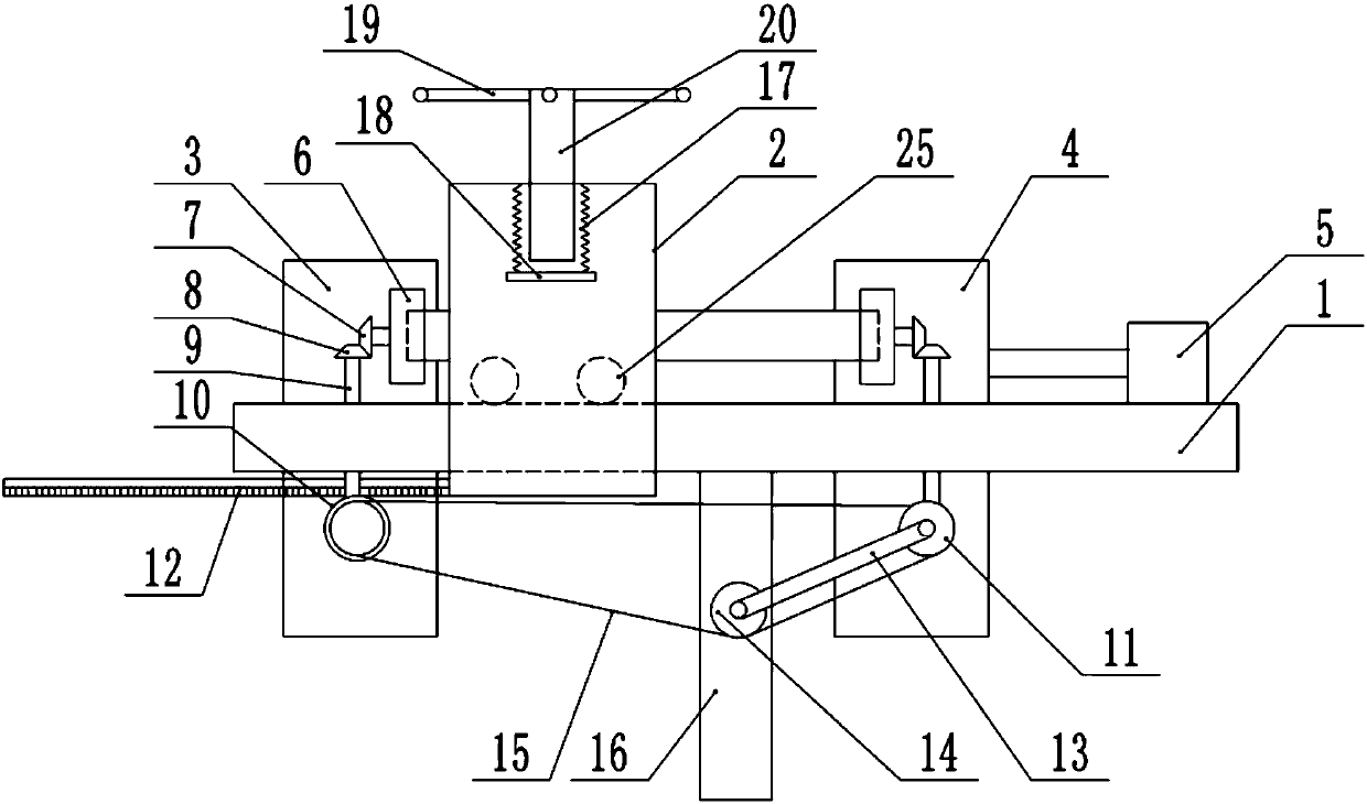
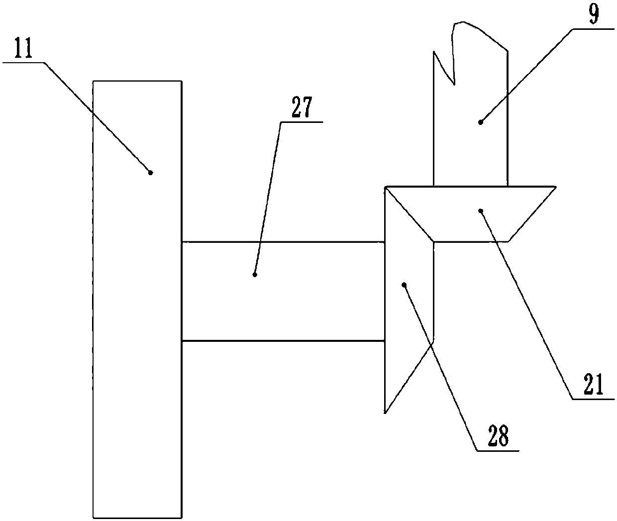
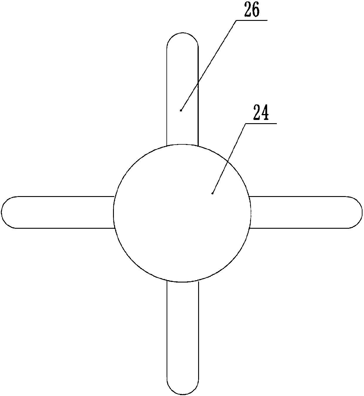
[0018] The reference signs in the drawings of the description include: workbench 1, printing frame 2, fixed plate 3, moving plate 4, cylinder 5, triangular chuck 6, second bevel gear 7, fourth bevel gear 8, vertical shaft 9 , spur gear 10, first sprocket 11, rack 12, connecting rod 13, second sprocket 14, chain 15, slide rail 16, spring 17, printing head 18, turret 19, screw rod 20, the third umbrella Gear 21, block 22, tightening bolt 23, tightening disc 24, bearing 25, tightening rod 26, transverse shaft 27, first bevel gear 28.

[0019] The embodiment is basically as attached Figure 1-Figure 5 Shown: a marking device for shaft parts, including a worktable 1 and a marking head 18, a printing frame 2 slides on the working table 1, and a bearing 25 is rotatably connected to the printing frame 2, and the working table 1 is provided with Guide rail, bearing 25 rolls along guide rail. The top of...


PUM


Abstract

The invention relates to a shaft part marking device. The shaft part marking device comprises a workbench and a marking head, wherein a marking frame is arranged on the workbench in a sliding mode; the top of the marking frame is in threaded connection with a screw; the marking head is positioned on the marking frame; a spring is connected between the marking frame and the marking head; a fixed plate and a movable plate are arranged at the two sides of the marking frame; a triangular chuck, a first chain wheel and a transverse shaft are arranged on each of the fixed plate and the movable plate; each transverse shaft is fixedly connected on the corresponding first chain wheel; a bevel gear is connected between each transverse shaft and the corresponding triangular chuck; a chain is engagedbetween two first chain wheels; a straight gear is connected on the first chain wheel at the left side; a rack which is engaged with the straight gear is connected on the marking frame; the bottom ofthe workbench is connected with a vertical slide rail; a second chain wheel engaged with the chain is connected on the slide rail in a sliding mode; and a connecting rod is rotatably connected betweenthe second chain wheel and the first chain wheel on the movable plate. The scheme realizes axial movement of the marking head along shaft parts, and the shaft parts also can automatically rotate in aradial direction.

Description

technical field [0001] The invention relates to the technical field of motorcycle parts processing, in particular to a marking device for shaft parts. Background technique [0002] For shaft parts on motorcycles, after the machining is completed, it is usually necessary to print some marks on the circumferential surface of the shaft parts, such as the production label and the like. During the mark printing process of shaft parts, multiple marks are often printed on different parts of the shaft parts, and the printing head is relatively stationary relative to the workbench, so it is necessary to continuously rotate the shaft parts and move the shaft Parts, so that the marking head is facing different parts of the shaft parts, so as to print multiple marks on different parts of the shaft parts. However, in this process, the shaft part must be moved axially while the shaft part is being rotated radially, and the operation process is relatively complicated. Contents of the in...

Claims


Application Information

Patent Timeline
Patent Type & Authority Applications(China)
IPC IPC(8): B41K3/36B41K3/44B41K3/62
CPCB41K3/36B41K3/44B41K3/62
Inventor 张科
Owner 重庆市合川区云天机械制造有限公司
Why Eureka
Try Eureka