Eureka AIR delivers breakthrough ideas for toughest innovation challenges, trusted by R&D personnel around the world.

Automobile rear floor structure

A rear floor and automobile technology, which is applied to the upper structure, upper structure sub-assembly, vehicle parts, etc., can solve the problems of poor stiffness and strength of the rear floor, NVH performance degradation, easy deformation and cracking, etc., to improve local stiffness and improve NVH performance, effect of increased weight

Inactive Publication Date: 2018-05-18
CHERY AUTOMOBILE CO LTD
View PDF9 Cites 0 Cited by
  • Summary
  • Abstract
  • Description
  • Claims
  • Application Information

AI Technical Summary

Problems solved by technology

[0004] The purpose of the present invention is to propose a car rear floor structure to solve the problems of poor rear floor rigidity and strength, easy deformation and cracking, easy resonance, NVH performance decline, etc., improve the performance of the rear floor structure, and at the same time meet Process requirements, no increase in weight and reduced vehicle cost, thereby improving market competitiveness

Method used


Image

  • Automobile rear floor structure
  • Automobile rear floor structure

Examples


Embodiment 1

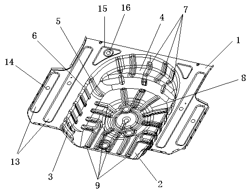
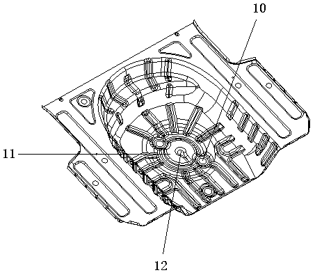
[0024] Such as figure 1 , 2 As shown, the car rear floor structure of the present invention includes an upper surface 1, a sinking surface 2 and a side elevation 3, and the sinking surface 2 is a "U"-shaped surface that is parallel and concave downwards from the upper surface 1, and the upper surface 1 The inner edge of the sunken surface extends vertically downward to the edge of the "U"-shaped sunken surface 2 to form the side elevation 3, so the side elevation 3 is a vertical "U" shape, and the arc inside the "U"-shaped side elevation 3 The shape part is a stepped boss 4, and reinforcement ribs are provided on the side facade 3, the sinking surface 2 and the stepped boss 4; 3 and the sinking surface 2 are transitioned through a circular arc, and the bending part of the stepped boss 4 is transitioned through a circular arc. Through the above settings, the structure of the rear floor of the automobile is simple, compact and coherent, strong in stability, strong and reliable...


PUM


Abstract

The invention provides an automobile rear floor structure which can effectively solve the problems that an automobile rear floor is poor in rigidity and strength and likely to deform and crack, resonance is likely to happen, and the NVH performance is reduced. The structure comprises an upper surface, a U-shaped sunken face recessed downwards in parallel from the upper surface and a side verticalface connecting the upper surface with the sunken face, the position located on the inner side of the side vertical face is a stepped boss, and reinforcing ribs are arranged on the side vertical face,the sunken face and the stepped boss. The rigidity of the automobile rear floor can be effectively improved, stress concentration can be reduced, each type of use performance of the structure is improved, and therefore the reliability, the safety and the comfort level of a whole automobile are improved; and the structure is reasonable in arrangement, stable, firm, technologically easy to achieve,low in cost, wide in universality and higher in market competitiveness.

Description

technical field [0001] The invention belongs to the technical field of automobile structure, in particular, the invention relates to an automobile rear floor structure for carrying a spare tire. Background technique [0002] With the rapid development of the automobile industry, it is particularly important to improve the reliability, safety and comfort of automobiles. In order to respond to the national call for energy conservation and emission reduction and to make their products more competitive, all automakers pay great attention to optimizing the structure to reduce weight and cost on the basis of making the structure meet various performances. [0003] The rear floor is the part of the rear body for placing spare tires and other on-board tools. Its area is generally a deep drawing area, and the yield strength of the materials used is generally low. When the rear floor is subjected to excitation from the road surface and the engine, it will bear various dynamic loads. ...

Claims


Application Information

Patent Timeline
IPC IPC(8): B62D25/20B62D43/10
CPCB62D25/20B62D43/10
Inventor 严婷仰荣德董宗岐廖小红
Owner CHERY AUTOMOBILE CO LTD
Why Eureka
Eureka Blog
Learn More