
Optical system for telescope

An optical system and telescope technology, applied in the field of telescopes, can solve the problems of coma, imaging chromatic aberration and spherical aberration, etc., and achieve the effect of improved structure, small chromatic aberration and spherical aberration, and bright imaging

Inactive Publication Date: 2018-05-18
NANTONG SCHMIDT OPTO ELECTRICAL TECH CO LTD
View PDF11 Cites 1 Cited by
  • Summary
  • Abstract
  • Description
  • Claims
  • Application Information

AI Technical Summary

Problems solved by technology

[0004] In similar telescope systems currently on the market, the chromatic aberration and spherical aberration of imaging are large, and coma aberration exists

Method used


Image

  • Optical system for telescope
  • Optical system for telescope
  • Optical system for telescope

Examples


Embodiment

[0044] The specific parameters of the optical system are shown in Table 1

[0045] .

[0046] Table 1

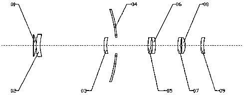
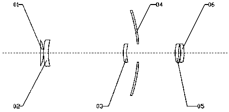
[0047] The focal length of the system is 2025mm, the field of view of the system is 60mm, the imaging area is 44mm, the limit level is 14.4, the power limit is 600X, the resolution is 0.46 arc seconds, and the back focus is 123.9mm.

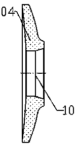
[0048] When the present invention is used, the light reflected by the object irradiates the reflection surface of the main reflector 04, after the main reflector 04 reflects the light, the light passes through the first lens 02 and irradiates on the secondary reflector 01, and the secondary reflector 01 reflects the light back, and passes through The second lens 03 passes through the opening 10 in the middle of the main mirror 04 after refraction, then passes through the third lens 05, the fourth lens 06, the fifth lens 07, the sixth lens 08, and the seventh lens 09 in sequence, and finally passes through the camera Or imaging in the human ...


PUM


Abstract

The invention relates to an optical system for a telescope. The optical system comprises a front end mirror group, a middle end mirror group and a tail end mirror group which are arranged from an object surface to an image surface in sequence. The front end mirror group, the middle end mirror group and the tail end mirror group are arranged at intervals. The optical system has the advantages thatthe design is reasonable, the structure is simple, and the structure of a main reflector is improved. The area of a central opening of the main reflector accounts for 10.8% of the total area of the main reflector, so that more light can be greatly collected, and imaging is brighter. A third lens and a fourth lens are used for correcting coma aberration and spherical aberration caused by optical paths of light reflected from the main reflector and a secondary reflector, so that color difference and the spherical aberration of imaging are smaller, and there is no coma aberration; a defocusing mirror group is added, and F / D is dropped to 10, so that imaging is brighter and clearer, the exposure time of a camera is shortened, the filming rate is increased, the view field of the system is effectively improved, and the imaging area is extensive.

Description

technical field [0001] The invention relates to the field of telescopes, in particular to an optical system for a telescope. Background technique [0002] The ratio of the focal length F to the diameter D of the objective lens of other telescope systems currently on the market is basically F / D=12, F / D=15. [0003] In similar telescope systems currently on the market, the central opening area of ​​the main mirror accounts for more than 15%-20% of the total area of ​​the main mirror, and the image is dark. [0004] In similar telescope systems currently on the market, the chromatic aberration and spherical aberration of imaging are large, and coma aberration exists. Contents of the invention [0005] In order to solve the above problems, the present invention proposes an optical system for a telescope, which has a reasonable design, a simple structure, and improves the structure of the main reflector. More light makes the imaging brighter; the third lens and the fourth len...

Claims


Application Information

Patent Timeline
Patent Type & Authority Applications(China)
IPC IPC(8): G02B23/02G02B23/00
CPCG02B23/02G02B23/00
Inventor 沈达忠
Owner NANTONG SCHMIDT OPTO ELECTRICAL TECH CO LTD
Learn More