
A battery charging automatic control circuit

An automatic control circuit and battery technology, applied in battery circuit devices, different battery charging, electric vehicles, etc., can solve the problems of high device cost and complex control, avoid signal interference, reduce coupling problems, and ensure isolation. Effect

Active Publication Date: 2020-10-16
HUAZHONG UNIV OF SCI & TECH
View PDF7 Cites 0 Cited by
  • Summary
  • Abstract
  • Description
  • Claims
  • Application Information

AI Technical Summary

Problems solved by technology

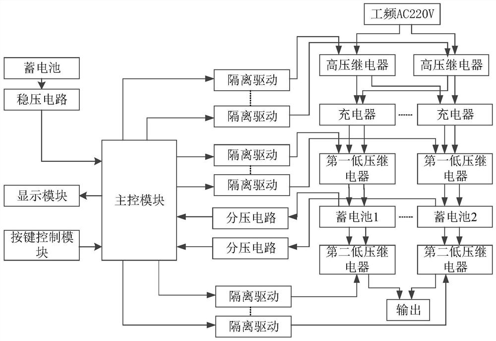
[0005] In view of the above defects or improvement needs of the prior art, the present invention provides an automatic control circuit for battery charging, thereby solving the technical problems of complex control and high device cost that currently exist in the use of microcontrollers as automatic control means

Method used


Image

  • A battery charging automatic control circuit
  • A battery charging automatic control circuit
  • A battery charging automatic control circuit

Examples


Embodiment Construction

[0039] In order to make the object, technical solution and advantages of the present invention clearer, the present invention will be further described in detail below in conjunction with the accompanying drawings and embodiments. It should be understood that the specific embodiments described here are only used to explain the present invention, not to limit the present invention. In addition, the technical features involved in the various embodiments of the present invention described below can be combined with each other as long as they do not constitute a conflict with each other.

[0040] Usually the output device used by the battery requires the use of "suspended ground" and is very reliable, which determines that the existing automatic charging control circuit cannot be applied to our actual application. Therefore, multiple relays are used in the present invention. They effectively ensure that the battery is always in a suspended state when it is exported to the outside ...


PUM


Abstract

The invention discloses an automatic control circuit for storage battery charging. The automatic control circuit comprises a high-voltage relay, a first low-voltage relay, a second low-voltage relay,a key control module and a main control module, wherein the main control module disconnects the high-voltage relay between a charger and a power frequency signal and a first low-voltage relay connected between the charger and the storage battery and connects the second low-voltage relay connected between the storage battery and the output to enable the storage battery to discharge, when key control signal is used for controlling a storage battery to discharge, the main control module disconnects the second low-voltage relay when the key control signal is used for controlling the storage battery to charge, and connects the high-voltage relay and the first low-voltage relay for charging when the voltage value of the storage battery is lower than a preset discharging voltage value, and disconnects the high-voltage relay and the first low-voltage relay to terminate the charging when the voltage value reaches a preset charging voltage value. According to the invention, the safety and stability are achieved, the control is standard, the operation is simple, the working state can be switched by one key, and the voltage of the storage battery can be effectively monitored.

Description

technical field [0001] The invention belongs to the field of battery charging automatic control, and more specifically relates to a battery charging automatic control circuit. Background technique [0002] Lead-acid batteries are widely used in production and life due to their advantages of stable voltage and low price. However, a common problem, regardless of the type of battery, is the possibility of emptying the charge. However, some power supply equipment needs stable and continuous power supply. Once the power is insufficient, it will inevitably cause it to fail to work normally. [0003] There have been many studies on the design of the automatic charging circuit for the battery. However, after research, it is found that the basic principle of the traditional automatic charging circuit is to divide the voltage from the output terminal of the charger and send it to the positive input terminal of the comparator as the reference voltage for charging control; The revers...

Claims


Application Information

Patent Timeline
Patent Type & Authority Patents(China)
IPC IPC(8): H02J7/00
CPCH02J7/0047H02J7/0077
Inventor 高丽张俊利王璐周乙楠周靖钧周呈熙
Owner HUAZHONG UNIV OF SCI & TECH
Learn More