Check patentability & draft patents in minutes with Patsnap Eureka AI!

Power-saving control circuit and control method thereof

A technology of power-saving control and control method, applied in the field of circuits, can solve the problems of exhausted battery and shortened battery life, and achieve the effect of zero power consumption

Inactive Publication Date: 2018-05-18
HAIER YOUJIA INTELLIGENT TECH BEIJING CO LTD
View PDF5 Cites 3 Cited by
  • Summary
  • Abstract
  • Description
  • Claims
  • Application Information

AI Technical Summary

Problems solved by technology

[0003] At present, this way of entering sleep mode can greatly reduce power consumption, but some devices still have a certain amount of power consumption in sleep mode
Even if it is left unused, when the user uses it again after a while, the battery power may have been exhausted, resulting in a shorter battery life

Method used


Image

  • Power-saving control circuit and control method thereof
  • Power-saving control circuit and control method thereof

Examples


Embodiment 1

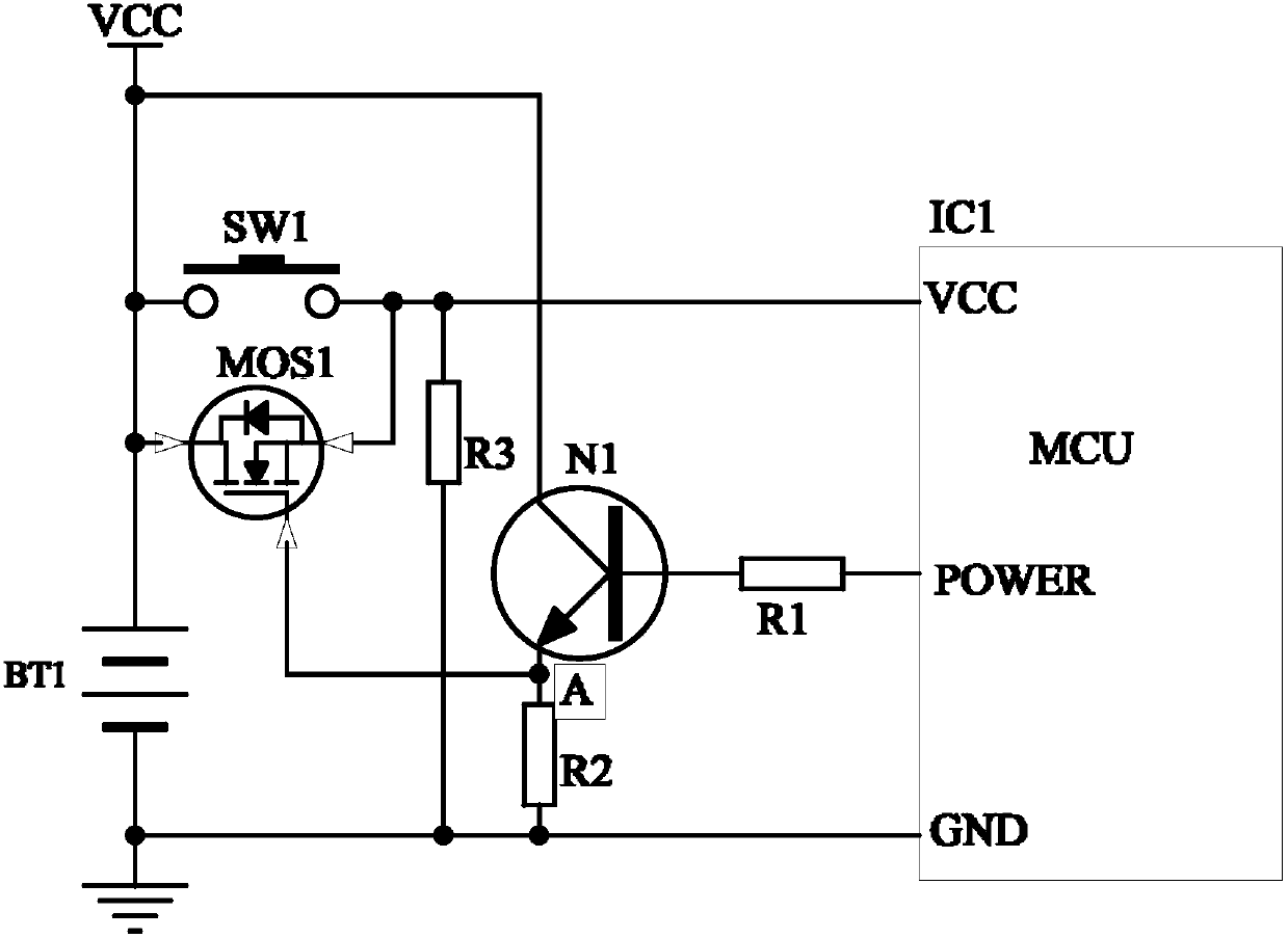
[0026] see figure 1 As shown, the power-saving control circuit of Embodiment 1 is used to connect with the power supply built in the device. The power-saving control circuit includes: a first switch SW1 and a second switch MOS1 connected in parallel, and the second switch MOS1 includes a first terminal, The second terminal and the third terminal, wherein the first terminal and the second terminal are respectively connected to two ends of the first switch SW1, and the third terminal is used as a control terminal.

[0027] The controller MCU includes a first power supply terminal VCC, a power supply control signal output terminal POWER and a second power supply terminal GND; the first power supply terminal VCC is connected to the positive pole of the power supply BT1 through the first switch SW1, and the second power supply terminal GND is connected to the positive pole of the power supply BT1. Negative pole; the power supply control signal output terminal POWER is connected to ...

Embodiment 2

[0037] The control method of the power-saving control circuit of Embodiment 2, wherein the power-saving control circuit is any one of the above-mentioned power-saving control circuits, and the control method includes:

[0038] When the first switch of the power-saving control circuit is turned on, the controller is powered on to work, and the output terminal of the power control signal of the controller outputs the first control signal to control the second switch of the power-saving control circuit to be turned on;

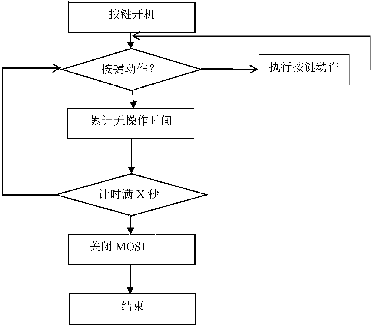
[0039] When the continuous off time of the first switch exceeds a preset threshold, the power supply control signal output terminal outputs a second control signal to control the second switch to be turned off, and the controller stops working when it is powered off.

[0040] Specifically, when the first switch is a key switch, the continuous off time of the first switch is a continuous non-operation time. Such as figure 2 As shown, the specific process may inc...


PUM


Abstract

The invention discloses a power-saving control circuit and a control method thereof. The power-saving control circuit comprises a first switch and a second switch which are connected in parallel, anda controller, wherein the second switch comprises a first end, a second end and a third end, the first end and the second end are connected with two ends of the first switch, the third end is taken asa control end, the controller comprises a first power source end, a power source control signal output end and a second power source end, the first power source end is connected with a positive poleof a supply power source through the first switch, the second power source end is connected with a negative pole of the supply power source, the power source control signal output end is connected with the control end of the second switch, when the first switch is conducted, a first control signal is outputted by the power source control signal output end and is used for controlling the second switch for conduction, when the continuous power failure time of the first switch surpasses the preset threshold, a second control signal is outputted by the power source control signal output end and isused for controlling the second switch for power failure. The power-saving control circuit is advantaged in that power consumption can be reduced, and service life of the power source is improved.

Description

technical field [0001] The invention relates to the technical field of circuits, in particular to a power-saving control circuit and a control method thereof. Background technique [0002] With the continuous improvement of people's consumption level and quality of life, various testing instruments continue to emerge. Such as skin tester, blood sugar tester, etc., these small devices are generally powered by batteries. Due to the relatively high power consumption during operation, the instrument will automatically enter sleep mode when the user does not use the instrument. [0003] At present, this way of entering sleep mode can greatly reduce power consumption, but some devices still have certain power consumption in sleep mode. Even if it is left unused, when the user uses it again after a period of time, the battery power may be exhausted, resulting in a shortened battery life. [0004] Therefore, it is urgent to develop a power-saving control circuit with zero power c...

Claims


Application Information

Patent Timeline
IPC IPC(8): H02J9/00
CPCH02J9/005Y02B70/30Y04S20/20
Inventor 董金运
Owner HAIER YOUJIA INTELLIGENT TECH BEIJING CO LTD
Features
  • R&D
  • Intellectual Property
  • Life Sciences
  • Materials
  • Tech Scout
  • Unparalleled Data Quality
  • Higher Quality Content
  • 60% Fewer Hallucinations
Learn More