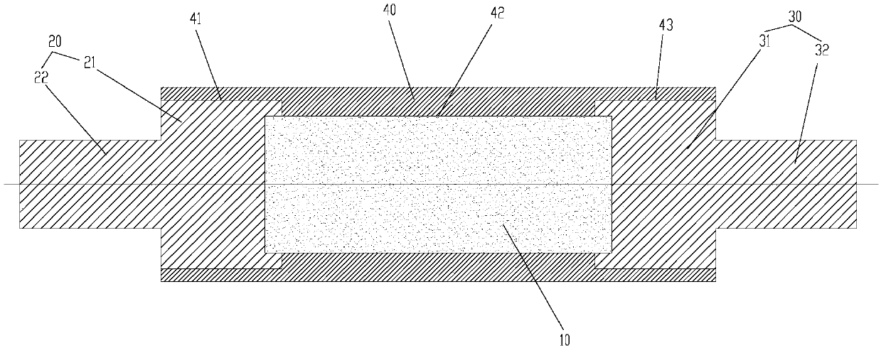
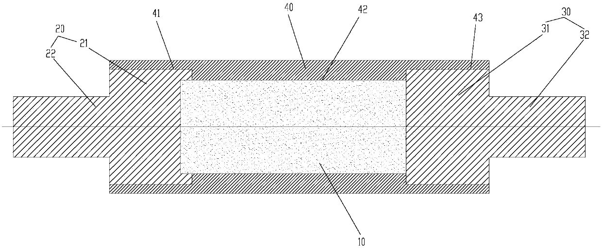
Rotor shaft assembly, rotor and motor

A technology for rotor shafts and components, applied in bearing assembly, bearing components, electric components, etc., can solve the problem of axis misalignment and achieve the effect of solving axis misalignment

Active Publication Date: 2018-05-18
GREE ELECTRIC APPLIANCES INC
View PDF4 Cites 5 Cited by
  • Summary
  • Abstract
  • Description
  • Claims
  • Application Information

AI Technical Summary

Problems solved by technology

[0003] The main purpose of the present invention is to provide a rotor shaft assembly, rotor and motor to solve the problem that the rotor shaft assembly in the prior art is prone to axis misalignment when assembling the end shaft and magnetic steel

Method used


Image

  • Rotor shaft assembly, rotor and motor
  • Rotor shaft assembly, rotor and motor
  • Rotor shaft assembly, rotor and motor

Examples


Embodiment Construction

[0024] It should be noted that, in the case of no conflict, the embodiments in the present application and the features in the embodiments can be combined with each other. The present invention will be described in detail below with reference to the accompanying drawings and examples.

[0025] It should be pointed out that the following detailed description is exemplary and intended to provide further explanation to the present application. Unless defined otherwise, all technical and scientific terms used herein have the same meaning as commonly understood by one of ordinary skill in the art to which this application belongs.

[0026] It should be noted that the terminology used here is only for describing specific implementations, and is not intended to limit the exemplary implementations according to the present application. As used herein, unless the context clearly dictates otherwise, the singular is intended to include the plural, and it should also be understood that wh...


PUM


Abstract

The invention provides a rotor shaft assembly, a rotor and a motor. The rotor shaft assembly comprises a magnetic core, a first end shaft, a second end shaft and a protection sleeve. A first through hole, a second through hole and a third through hole are formed in the protection sleeve in sequence, the first end shaft penetrates through the first through hole, at least part of the magnetic core is arranged in the second through hole, and the second end shaft penetrates through the third through hole; the minimum distance between the center line of the protection sleeve and the hole wall of the first through hole is a, the minimum distance between the center line of the protection sleeve and the hole wall of the second through hole is b, and the minimum distance between the center line ofthe protection sleeve and the hole wall of the third through hole is c, wherein one or two of a and c are not equal to b. According to rotor shaft assembly, the problem is solved that in the prior art, when the end shafts and magnetic steel of a rotor shaft assembly are assembled, and the axis is not easily centered.

Description

technical field [0001] The invention relates to the field of motors, in particular to a rotor shaft assembly, a rotor and a motor. Background technique [0002] An existing high-speed permanent magnet motor rotor structure, please refer to figure 1 , the rotating shaft is spliced ​​by three sections, using the whole cylindrical magnetic steel 3, using the interference fit between the alloy sheath 4 and the three sections of the main shaft to transmit the torque, wherein, the first rotating shaft end piece 1 and the second rotating shaft end piece 2 All are non-magnetic materials. When the rotor with this structure is assembled with the first rotating shaft end piece 1 and the cylindrical magnetic steel 3 , since there is no relevant structural positioning, it is very easy for the axis to be misaligned. Contents of the invention [0003] The main purpose of the present invention is to provide a rotor shaft assembly, a rotor and a motor, so as to solve the problem that the...

Claims


Application Information

Patent Timeline
Patent Type & Authority Applications(China)
IPC IPC(8): H02K7/00F16C3/02
CPCH02K7/003F16C3/023H02K1/2726F16C2204/60F16C2226/12F16C2380/26
Inventor 彭利明贾金信张小波刘健宁张芳李广海郭长光魏琼李忠雨闫瑾梁建东熊博文王泽业
Owner GREE ELECTRIC APPLIANCES INC
Why Eureka
Try Eureka