Punching and shearing method of assembly type heavy hydraulic punching and shearing machine with high punching and shearing precision

A punching and shearing machine and assembled technology, which is applied in the direction of feeding device, positioning device, storage device, etc., can solve the problems of good economic benefits, and achieve the effects of cost reduction, convenient operation, and reduced strength

Active Publication Date: 2018-05-22
ANHUI ZHONGYI MACHINE TOOL MFG
View PDF9 Cites 0 Cited by
  • Summary
  • Abstract
  • Description
  • Claims
  • Application Information

AI Technical Summary

Problems solved by technology

[0014] The purpose of the present invention is to solve the existing problems of the punching and shearing machine, and provides a punching and shearing method of an assembled heavy-duty hydraulic punching and shearing machine with high punching and shearing precision; the present invention solves the various defects of the existing punching and shearing machine, improves The use effect of the punching and shearing machine is improved, and the transformation cost of the existing punching and shearing machine is low, and the economic benefit is good

Method used


Image

  • Punching and shearing method of assembly type heavy hydraulic punching and shearing machine with high punching and shearing precision
  • Punching and shearing method of assembly type heavy hydraulic punching and shearing machine with high punching and shearing precision
  • Punching and shearing method of assembly type heavy hydraulic punching and shearing machine with high punching and shearing precision

Examples


Embodiment 1

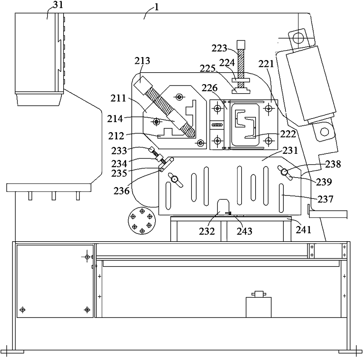
[0064] combine figure 1 , an assembled heavy-duty hydraulic punching and shearing machine with high punching and shearing precision in this embodiment, a pressing mechanism is arranged on the front of the punching and shearing machine body 1, and the pressing mechanism includes a pressing assembly with 3 stations ;in:

[0065] The first pressing assembly includes a first material limiting plate 211, a first pressing screw 213 and a first fixing sleeve 214, the first material limiting plate 211 is fixed on the fuselage 1 by bolts, and the first material limiting plate 211 is provided with a There is a first feeding chute 212, and the first feeding chute 212 is an irregular "L"-shaped structure. The first compression screw 213 is arranged on the first material limiting plate 211 through the first fixed sleeve 214, and the first compression screw 213 can move toward the top angle direction of the first feeding groove 212. The first pressing assembly of this embodiment is mainly...

Embodiment 2

[0073] combine Figure 5 , Figure 6 and Figure 7 , an assembled heavy-duty hydraulic punching and shearing machine with high punching and shearing precision in this embodiment includes an oil cylinder fixing mechanism. In this embodiment, a "T-shaped" side plate groove 321 is set on the oil cylinder side plate 32 of the hydraulic cylinder 31, and a "T-shaped" side plate boss 111 is correspondingly set on the fuselage side plate 11 of the fuselage 1, and in the machine A first side plate fixing hole 112 is provided on both sides of the body side plate 11 in the length direction, and a second side plate fixing hole 322 is provided on both sides of the cylinder side plate 32 in the length direction.

[0074] When assembling the punching and shearing machine, insert the "T-shaped" side plate boss 111 on the side of the fuselage 1 into the "T-shaped" side plate groove 321 on the side of the hydraulic cylinder 31, and then use the second fastening bolt 33 to pass through the fir...

Embodiment 3

[0076] combine Figure 8 , Figure 9 and Figure 10 , an assembled heavy-duty hydraulic punching and shearing machine with high punching and shearing precision in this embodiment is an oil cylinder fixing mechanism with another structural design. In this embodiment, a dovetail-shaped boss is provided on the cylinder side plate 32 of the hydraulic cylinder 31 , and correspondingly, a dovetail-shaped groove is provided on the fuselage side plate 11 of the fuselage 1 .

[0077] When assembling the punching and shearing machine, insert the dovetail-shaped boss on the side of the hydraulic cylinder 31 into the dovetail-shaped groove on the side of the fuselage, and then use the second fastening bolt 33 to pass through the fixing hole 112 of the first side plate and the second side plate. The plate fixing hole 322 securely connects the hydraulic cylinder 31 and the fuselage 1 . Since the contact surface between the hydraulic cylinder 31 and the fuselage 1 is a matching dovetail s...


PUM


Abstract

The invention discloses a punching and shearing method of an assembly type heavy hydraulic punching and shearing machine with high punching and shearing precision, and belongs to the technical field of machining processing equipment. The punching and shearing machine includes a material pressing mechanism, a lower mould seat compressing mechanism, a back material blocking mechanism, and an oil cylinder fixing mechanism. Wherein a hydraulic oil cylinder in the oil cylinder fixing mechanism and a punching and shearing machine body are connected through a second fastening bolt, and the contact surfaces of the hydraulic oil cylinder and the machine body are inclined wedge surfaces matched in pairs. The side surface of the hydraulic oil cylinder is provided with a groove or a convex table, andcorrespondingly, the side surface of the machine body is provided with a convex table or a groove matched with the groove or the convex table. The convex table is a T-shaped convex table or a swallowtail shaped convex table. The groove is a T-shaped groove or a swallow tail shaped groove, wherein the size of the T-shaped groove or the swallow tail shaped groove is matched with the size of the convex table. According to the punching and shearing method, the using effect of the punching and shearing machine is improved; the improvement cost to an existing punching and shearing machine is low; and the economic efficiency is good.

Description

[0001] The patent application of the present invention is a divisional application with the application number: 2016108350619. The filing date of the original application is: 2016-9-20. The name of the invention is: an assembled heavy-duty hydraulic punching and shearing machine with high punching and shearing precision and its punching and shearing method. technical field [0002] The invention relates to the technical field of mechanical processing equipment, more specifically, to an assembled heavy-duty hydraulic punching and shearing machine and a punching and shearing method thereof with high punching and shearing precision for punching and punching a plate or profile. Background technique [0003] Currently used punching and shearing machines mainly include flywheel punching and shearing machines and hydraulic combined punching and shearing machines, which gradually develop from single punching, shearing or bending functions to multifunctional functions. Among them, th...

Claims


Application Information

Patent Timeline
Patent Type & Authority Applications(China)
IPC IPC(8): B21D35/00B21D28/02B21D28/24B21D43/00B21D28/14B21D28/34
CPCB21D28/02B21D28/14B21D28/243B21D28/34B21D35/001B21D43/003
Inventor 叶元义叶良鹏臧文富
Owner ANHUI ZHONGYI MACHINE TOOL MFG
Why Eureka
Try Eureka