Clamp for automatic milling of inner and outer tooth profiles of pliers body

An automatic milling and fixture technology, which is applied in the direction of manufacturing tools, metal processing equipment, metal processing machinery parts, etc., can solve the problems of low production efficiency, high labor intensity, and inability to planar processing and positioning, so as to achieve high processing production efficiency and avoid manual labor. The trouble of sorting and the effect of controllable product quality

Active Publication Date: 2018-05-22
湖南精专自动化技术有限公司
View PDF5 Cites 1 Cited by
  • Summary
  • Abstract
  • Description
  • Claims
  • Application Information

AI Technical Summary

Problems solved by technology

[0003] In the existing pliers head processing technology, when manufacturing pliers, the four elements on the pliers head are completed by two processes and divided into eight processing stations, and the left pliers body is clamped four times and processed four times. station; the right pliers body has four clamping and four processing stations; and the existing technology is mostly manual clamping, resulting in low production efficiency and high labor intensity
[0004] When processing the inner and outer tooth profiles of the pliers (i.e. the special-shaped structure 808 on the inner surface and the special-shaped structure 807 on the outer surface), traditional methods cannot be used for plane processing and positioning. The plane structure is special-shaped, and the processing method is head processing. Therefore, a brand-new structure is needed to limit the position of the pliers body, and at the same time, it is convenient for machining

Method used


Image

  • Clamp for automatic milling of inner and outer tooth profiles of pliers body
  • Clamp for automatic milling of inner and outer tooth profiles of pliers body
  • Clamp for automatic milling of inner and outer tooth profiles of pliers body

Examples


Embodiment Construction

[0030] In order to enable those skilled in the art to better understand the technical solution of the present invention, the present invention will be described in detail below in conjunction with the accompanying drawings. The description in this part is only exemplary and explanatory, and should not have any limiting effect on the protection scope of the present invention. .

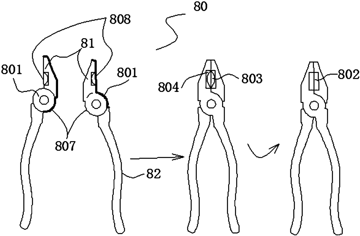
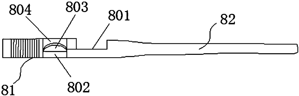
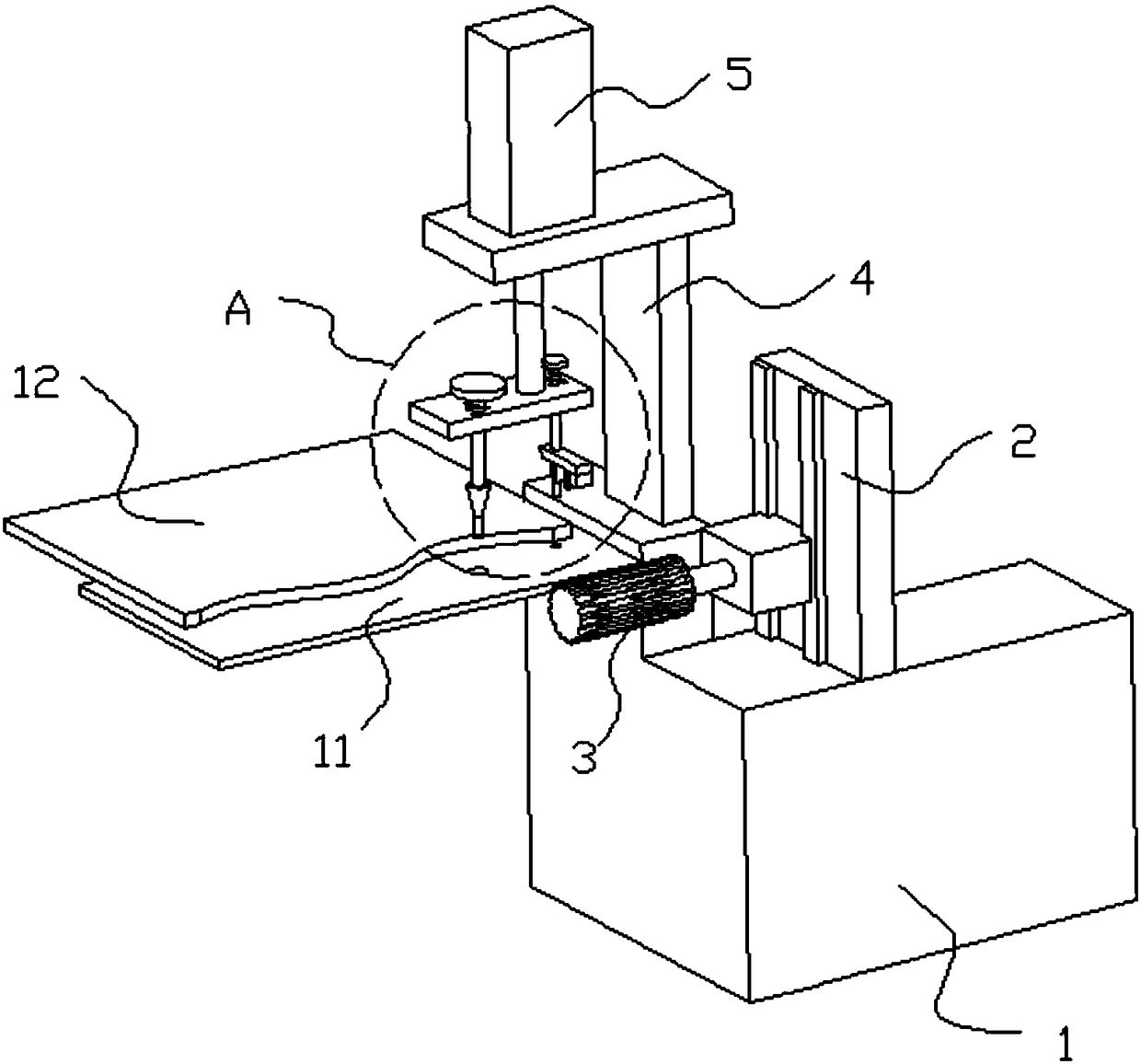
[0031] Such as Figure 3-Figure 6 As shown, the specific structure of the present invention is: a fixture for automatic milling of tooth profiles on both sides inside and outside the pliers, which is arranged on the base 1 and is at the feeding front end of the milling cutter support 2 and the milling cutter 3 , a clamp support 4 is arranged side by side with the milling cutter support 2, a support drive 5 is arranged above the clamp support 4, and a guide rod support 631 is fixed on the lower connecting rod connected with the support drive 5, and Positioning rod 61 and clamp rod 62 are arranged side ...


PUM


Abstract

The invention discloses a clamp for automatic milling of inner and outer tooth profiles of a pliers body. According to the clamp for automatic milling of the inner and outer tooth profiles of the pliers, a clamp body is arranged on a base and is arranged at a milling cutter support and the feeding front end of a milling cutter; a clamp support is arranged side by side with the milling cutter support; a support driver is arranged on the clamp support; a guide rod support is fixed to a lower connecting rod which is in connected to the support driver; a positioning rod and a clamp rod are arranged under the guide rod support side by side at interval; a positioning rod hole and a clamp rod hole are correspondingly formed in a machining plate below the positioning rod and the clamp rod; a clamphead is arranged on the clamp rod; and the positioning rod corresponds to a millstone hole of the pliers body. The clamp for automatic milling of the inner and outer tooth profiles of the pliers bodyhas the advantages that the pliers body can be conveniently automatically discharged and placed for machining, the pliers body can be stably and efficiently fixed, technical support can be provided for efficient production, and subsequent automatic machining and feeding can be facilitated.

Description

technical field [0001] The invention belongs to the field of hardware tool manufacturing, and relates to a processing tool for pliers, in particular to a fixture used for automatic milling processing of internal and external tooth profiles of pliers. Background technique [0002] Pliers are a hardware tool that is widely used, and the head part of the pliers is the main working element of the pliers, which is used to cut electric wires, iron wires or thin iron sheets. The functional area of ​​the pliers head generally includes the following elements: inner cutting edge, outer cutting edge, square mouth, grinding disc, such as Figure 1-Figure 2 As shown, the pliers body 80 is composed of two symmetrical halves of the left and right centers, which respectively include a pliers head 81 and a pliers handle 82; on the pliers head 81, an outer cutting edge 802, an inner cutting edge 803 and Square opening 804, and grinding disc 801 for assembly. [0003] In the existing pliers h...

Claims


Application Information

Patent Timeline
Patent Type & Authority Applications(China)
IPC IPC(8): B23Q3/06
CPCB23Q3/062Y02P70/10
Inventor 王再德王胜得王恒王琼
Owner 湖南精专自动化技术有限公司
Why Eureka
Try Eureka