

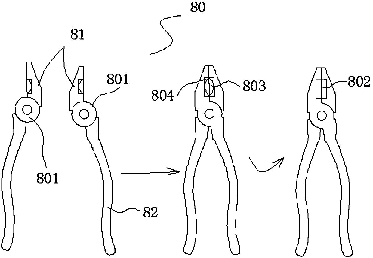
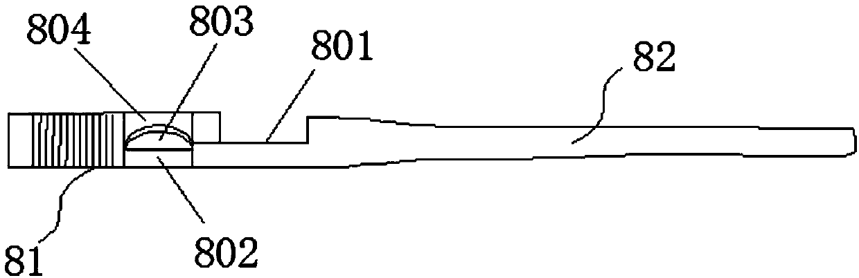
Mechanism used for continuous milling machining of special shapes and thread shapes on inner and outer surfaces of heads of pliers
A milling and pliers technology, applied in the field of hardware tool manufacturing, can solve the problems of inability to achieve automatic processing and feeding, not stacking in a row according to the order, and low production efficiency, so as to facilitate automatic processing and feeding, and control product quality. , the effect of high production efficiency
- Summary
- Abstract
- Description
- Claims
- Application Information
AI Technical Summary
Problems solved by technology
Method used
Image

Examples
Embodiment Construction
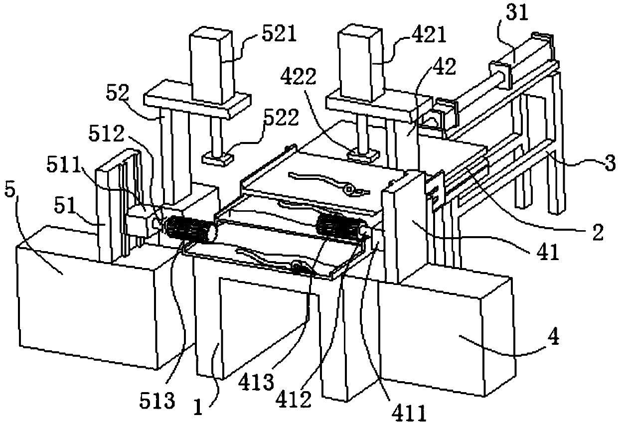
[0032] In order to enable those skilled in the art to better understand the technical solution of the present invention, the present invention will be described in detail below in conjunction with the accompanying drawings. The description in this part is only exemplary and explanatory, and should not have any limiting effect on the protection scope of the present invention. .
[0033] Such as Figure 3-Figure 5 As shown, the specific structure of the present invention is: a mechanism for continuous milling of special-shaped teeth on both sides of the pliers head, which includes a processing seat 1 and stacked processing layers arranged on it, each processing layer from top to bottom The bottoms are stacked one after the other and protrude forward one by one, and the materials to be processed move forward layer by layer from top to bottom; each layer is spaced from each other and there is a push plate layer 2 for coordinating activities in it, and limit baffles are set on both...
PUM
 Abstract
Description
Claims
Application Information