Milling machine waste collector

A technology for waste collection and milling machines, applied in metal processing machinery parts, maintenance and safety accessories, metal processing equipment, etc.

Inactive Publication Date: 2018-05-22
孙培宗
View PDF7 Cites 5 Cited by
  • Summary
  • Abstract
  • Description
  • Claims
  • Application Information

AI Technical Summary

Problems solved by technology

[0005] Aiming at the deficiencies in the prior art, the purpose of the present invention is to provide a waste collector for milling machines to solve the problem that when the prior art is used, after collecting scraps such as iron filings, it is easy to remove the iron filings in the collection box or collect the collected iron filings. When handling such as moving, it is easy to cause vibration and splash of iron filings, which will cause the collected iron filings to fall to the bottom plate, causing danger when trampling and falling into the clothes of workers, causing inconvenience.

Method used


Image

  • Milling machine waste collector
  • Milling machine waste collector
  • Milling machine waste collector

Examples


Embodiment Construction

[0024] In order to make the technical means, creative features, achievement goals and effects realized by the present invention easy to understand, the present invention will be further described below with reference to the specific embodiments.

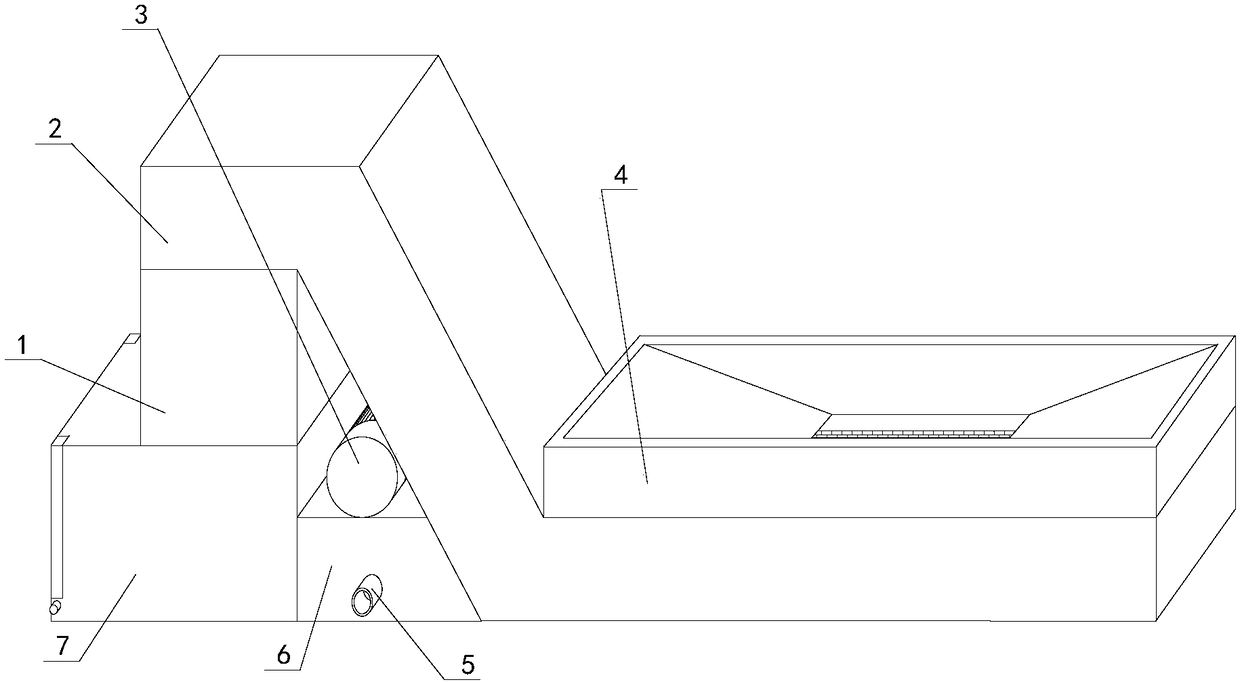
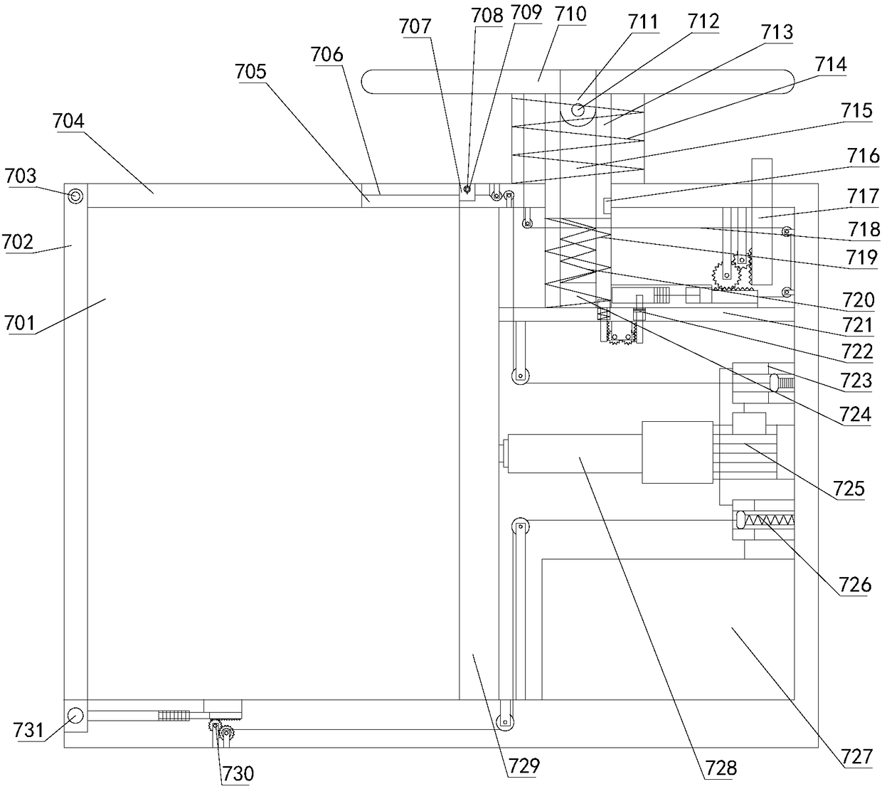
[0025] see Figure 1-Figure 7, the present invention provides a technical scheme of a milling machine waste collector: its structure includes a feeding groove 1, a lifter 2, an extraction motor 3, a collection seat 4, a liquid discharge port 5, an extraction seat 6, and a collection compression box 7. The lifter 2 is Z-shaped, a collecting seat 4 is welded on the right side of the top end, and a feeding receiving groove 1 is welded on the left side of the bottom end. The extraction seat 6 is locked and connected, the right end of the extraction seat 6 is welded with the lifter 2, and the extraction motor 3 is locked at the top. Box body 704, collecting and feeding port 705, feeding induction baffle 706, trigger assembly head 707, tr...


PUM


Abstract

The invention discloses a milling machine waste collector. The milling machine waste collector comprises a discharging receiving groove, a lifter, a pumping motor, a collection base, a discharge outlet, a pumping base and a collection and compression box; the lifter is shaped like a Z, the collection base is welded to the right side of the top, the discharging receiving groove is welded to the left side of the bottom, the bottom of the discharging receiving groove is vertically locked to the right side of the top of the collection and compression box in a locked mode, the pumping base is locked to the right end, the right end of the pumping base is welded to the lifter, and the pumping motor is locked to the top; when a user uses the equipment, the equipment can automatically conduct solid-liquid separation on waste by means of a mechanism composed of a gear, a stay cord, an ejector rod, a spring and the like, quantitative solid accumulation is conducted, and then the waste can be discharged into the compression box to be controlled to be compressed, the compression box of the equipment can be compressed and controlled to be deenergized when a box cover is opened and feeding is conducted, the safety in use is guaranteed, the equipment can compress and collect the waste better, danger caused by vibration spill is prevented, and use is facilitated.

Description

technical field [0001] The invention relates to a milling machine waste collector, belonging to the field of milling machine waste collectors. Background technique [0002] Compared with the horizontal milling machine, the main difference between the vertical milling machine and the horizontal milling machine is the vertical arrangement of the spindle. In addition to the different spindle arrangement, the worktable can be lifted up and down. The milling cutter used in the vertical milling machine is relatively flexible and has a wide range of applications. , Machine clamping cutter head, drill bit to carry out keyway milling, plane milling, boring and other processes. After the machining process of the large-scale milling machine is completed, a lot of iron filings or oil will be produced on the plane at the bottom of the milling machine. If it is not handled in time, it is easy to cause the iron filings to pierce the feet of the staff or pollute the operating environment. ...

Claims


Application Information

Patent Timeline
Patent Type & Authority Applications(China)
IPC IPC(8): B23Q11/00
CPCB23Q11/0067
Inventor 不公告发明人
Owner 孙培宗
Why Eureka
Try Eureka