Charging-stopping pulse charging device

A technology of pulse charging and charging unit, applied in the field of electronics, can solve the problems of fragile charging tubes, increasing the overall scrapping and damage of chargers, etc.

Inactive Publication Date: 2018-05-22
CHONGQING NINGLAI SCI & TRADE
View PDF0 Cites 0 Cited by
  • Summary
  • Abstract
  • Description
  • Claims
  • Application Information

AI Technical Summary

Problems solved by technology

[0008] The reason for the lack of current products is that there is no constant current and pulse charging circuit, and this circuit has a relatively simple circuit, and can flexibly adjust the relationship between charging and stopping, and the second is that it does not have a limited voltage. A circuit that combines the end of charging (this method is suitable for activated batteries) and the end of timing (this method is suitable for charging non-activated batteries and a large class of batteries such as acid)
The third is that there is no way to use active components for conversion to solve the problem that the charging tube is fragile
If the switch tube is in a pulsed state, it is more likely to become damaged and increase the overall scrapping of the charger

Method used


Image

  • Charging-stopping pulse charging device
  • Charging-stopping pulse charging device

Examples


Embodiment Construction

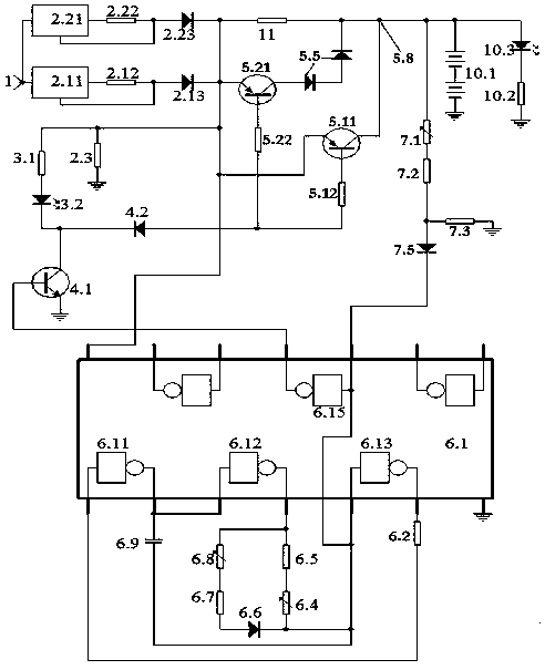
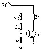
[0089] figure 1 An example of an implementation artifact is given, figure 2 Example of detection map in implementation.

[0090] 1. Select components: the gate in the ring oscillation unit is welded by the inverter inside the integrated circuit CD4069.

[0091] The triode for charging work and the triode for charging backup are PNP triodes, and the triodes for the interface are NPN triodes.

[0092] The charging switching circuit consists of two or three diodes connected in series.

[0093] The voltage regulator is composed of three-terminal integrated voltage regulator circuit.

[0094] 2. Make the circuit control board, welding components: connect figure 1 Make the circuit control board according to the schematic diagram, connect figure 1 Schematic of soldered components.

[0095] 3. Power-on inspection and debugging.

[0096] Check that the welding is correct, and you can conduct power-on inspection and debugging.

[0097] 1. Check the constant current source par...


PUM


Abstract

The invention discloses a charging-stopping pulse charging device, and belongs to the technical field of electronics. The device consists of a constant current source, a process display unit, an interface unit, a charging unit, an annular oscillating unit, a finishing change-over switch, a timing finishing unit, a voltage limiting finishing unit, a load unit, and a trickle resistor. The high and low output of the annular oscillating unit control the on/off of the interface unit, and the interface unit controls the charging unit to be turned on or off, thereby forming pulse-type charging. A current of the charging unit is supplied by the constant current source, so the mode is a constant current charging mode. The timing finishing unit and the voltage limiting finishing unit are switched through the finishing change-over switch, so the device is flexible and reliable. The timing finishing unit and the voltage limiting finishing unit are started, and the annular oscillating unit stops vibrating. Meanwhile, the charging unit is turned off. The trickle resistor supplies a trickle current to a charged battery. After implementation, the device achieves the scientific charging and maximumcharging of a rechargeable battery, thereby prolonging the service life of the charged battery to the greatest extent, enlarging the capacity of the charged battery to the greatest extent, and achieving the social environmental protection.

Description

technical field [0001] It belongs to the field of electronic technology. Background technique [0002] With the enrichment of modern life, there are more and more types of electrical appliances using batteries, such as digital machines, mobile phones, etc., and many types of chargers have appeared for this reason, but there are still many types of low-carbon and environmentally friendly charging circuits in these types. exist. [0003] One of its meanings is that in current products, the charging director, which is the circuit transistor that connects and shuts off the charging, is easily damaged. Once damaged, the charger becomes garbage. According to statistics, this failure has become the main failure point of the charger. It is a great waste to turn it into garbage just because of this damage. cost, so people are often throwing away). [0004] The second meaning is that during the charging process, the battery is not charged scientifically, which affects the capacity ...

Claims


Application Information

Patent Timeline
Patent Type & Authority Applications(China)
IPC IPC(8): H02J7/00
CPCH02J7/0047H02J7/00711
Inventor 不公告发明人
Owner CHONGQING NINGLAI SCI & TRADE
Why Eureka
Try Eureka