Low-carbon silicon controlled rectifier type environmentally friendly charger

A charger and environmental protection technology, applied in the electronic field, can solve the problems of the charging tube being fragile, damaged, increasing the overall scrapping of the charger, etc., and achieve the effect of streamlining the circuit and reducing the power output

Inactive Publication Date: 2017-03-15
CHONGQING NINGLAI SCI & TRADE
View PDF4 Cites 0 Cited by
  • Summary
  • Abstract
  • Description
  • Claims
  • Application Information

AI Technical Summary

Problems solved by technology

[0008] The reason for the lack of current products is that there is no constant current and pulse charging circuit, and this circuit has a relatively simple circuit, and can flexibly adjust the relationship between charging and stopping, and the second is that it does not have a limited voltage. A circuit that combines the end of charging (this method is suitable for activated batteries) and the end of timing (this method is suitable for charging non-activated batteries and a large class of batteries such as acid)
The third is that there is no way to use active components for conversion to solve the problem that the charging tube is fragile
If the switch tube is in a pulsed state, it is more likely to become damaged and increase the overall scrapping of the charger

Method used


Image

  • Low-carbon silicon controlled rectifier type environmentally friendly charger
  • Low-carbon silicon controlled rectifier type environmentally friendly charger
  • Low-carbon silicon controlled rectifier type environmentally friendly charger

Examples


Embodiment Construction

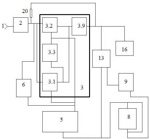
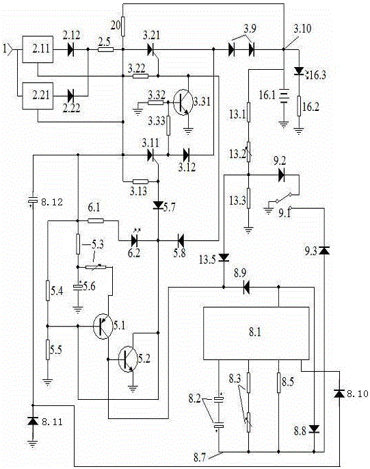
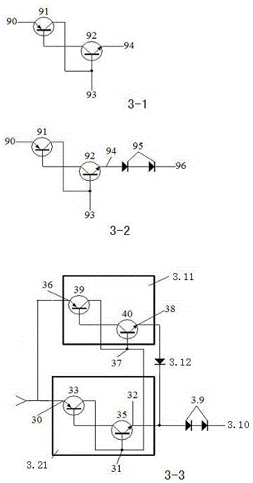
[0093] figure 1 , 2 , 3, 4, 5 examples show a kind of production scheme in the implementation of low-carbon thyristor type environmental protection charger.

[0094] 1. Selection of components: The cathode series diodes that make up the innovative silicon controlled rectifier are composed of two surface-mounted diodes connected in series. All thyristors are welded one-way thyristors. The charging conversion tube is an NPN triode. Diodes are surface-bonded diodes, and there are no special requirements for other resistance-capacitance components.

[0095] 2. Plate making and welding: according to figure 2 Make the circuit control board and press the connection figure 2 Schematic for soldering.

[0096] 3. Power on, check and debug.

[0097] 1. Power-on inspection and debugging of the constant current unit.

[0098] A. If Figure 4 As shown, solder a dummy load instead of the battery being charged. Connect a triode to form an adjustable voltage regulator analog circuit...


PUM


Abstract

The invention relates to a low-carbon silicon controlled rectifier type environmentally friendly charger and belongs to the electronic technical field. The low-carbon silicon controlled rectifier type environmentally friendly charger is composed of a constant-current power source, a charging unit, a pulse unit, a process indication unit, a timing termination unit, a selection unit, a voltage limiting termination unit, a load unit and a trickle resistor. The charging unit is controlled by the oscillation of the pulse unit to form a pulse form; and the power source of the charging unit is provided by the constant-current power source, and constant-current charging can be realized. The timing termination unit and the voltage limiting termination unit enable two termination modes; when voltage limiting termination is selected, timing termination does not act; as for a battery having a requirement for charging time, the timing termination is selected, and the voltage limiting termination is not enabled; and therefore, selection is flexible and convenient. According to the charging unit of the charger of the invention, two innovative silicon controlled rectifiers are in special parallel connection; under normal circumstances, only one silicon controlled rectifier works, and the other silicon controlled rectifier is adopted as a backup silicon controlled rectifier; and when one of the silicon controlled rectifiers is damaged, the other silicon controlled rectifier actively substitutes the damaged silicon controlled rectifier; and therefore, the service life of the charger can be greatly prolonged.

Description

technical field [0001] It belongs to the field of electronic technology. Background technique [0002] With the enrichment of modern life, there are more and more types of electrical appliances using batteries, such as digital machines, mobile phones, etc., and many types of chargers have appeared for this reason, but there are still many types of low-carbon and environmentally friendly charging circuits in these types. exist. [0003] One of its meanings is that in current products, the charging director, which is the circuit transistor that connects and shuts off the charging, is easily damaged. Once damaged, the charger becomes garbage. According to statistics, this failure has become the main failure point of the charger. It is a great waste to turn it into garbage just because of this damage. cost, so people are often throwing away). [0004] The second meaning is that during the charging process, the battery is not charged scientifically, which affects the capacity ...

Claims


Application Information

Patent Timeline
Patent Type & Authority Applications(China)
IPC IPC(8): H02J7/00
Inventor 宁永敭宁永健
Owner CHONGQING NINGLAI SCI & TRADE
Why Eureka
Try Eureka