Explosion center positioning device

A technology of positioning device and measuring device, applied in the direction of measuring device, using mechanical device, mechanical measuring device, etc., can solve the problems of high maintenance cost, limited range of measurable angles, affecting the normal test of explosion parameters, etc., and achieve the effect of low cost

Inactive Publication Date: 2018-05-25
XIAN MODERN CHEM RES INST
View PDF8 Cites 10 Cited by
  • Summary
  • Abstract
  • Description
  • Claims
  • Application Information

AI Technical Summary

Problems solved by technology

There are following problems in the method of using high-speed camera to determine the center of explosion: 1. The positioning scale will interfere with the explosion field and affect the normal test of other explosion parameters; 2. The high-speed camera is expensive, and the test process may be damaged by fragments produced by the explosion. The maintenance cost is high; 3. The sampling frequency of the high-speed camera is heavily affected by the intensity of the ambient light. When the light is insufficient, the sampling frequency needs to be reduced to shoot, and it may not be possible to accurately capture photos that can effectively interpret the location of the explosion center; 4. Use a high-speed camera to measure the explosion The center can only measure the detonation center position of the explosion process within the field of view of the camera, and the range of measurable angles is limited

Method used


Image

  • Explosion center positioning device
  • Explosion center positioning device
  • Explosion center positioning device

Examples


Embodiment 1

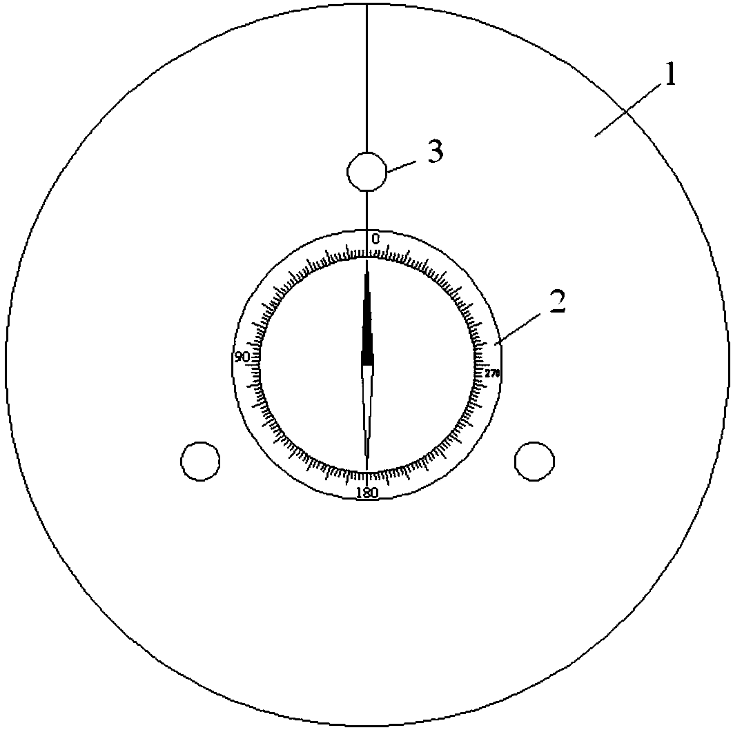
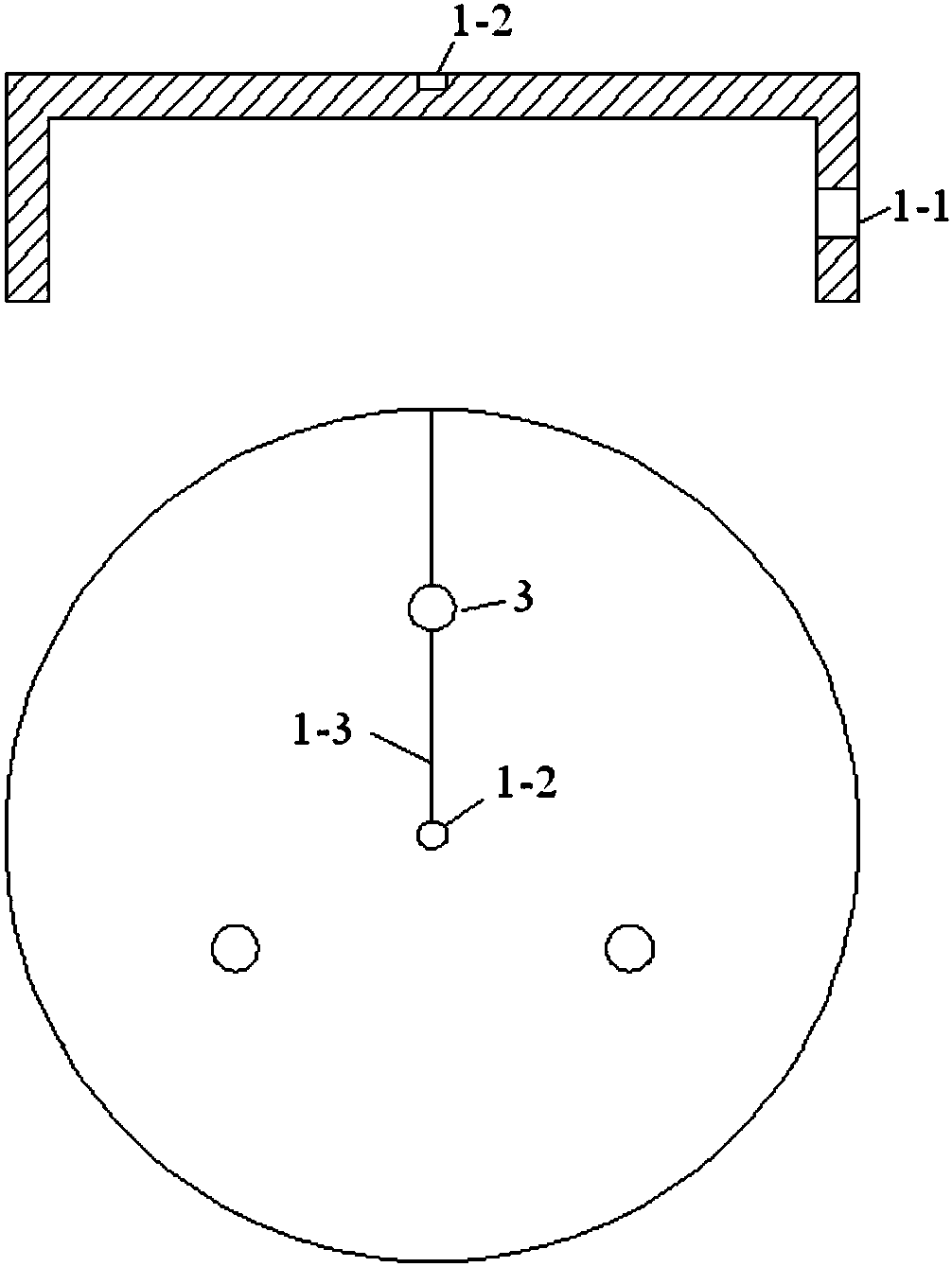
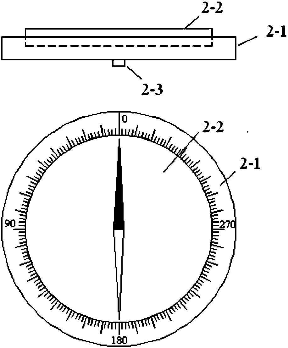
[0012] The present invention sees figure 1 , figure 2 and image 3 , including test base 1 and direction adjuster 2. The test base 1 is a cylindrical shell structure with an open lower end, which should be made of metal materials or other high-strength non-metallic materials, and a circular cable hole 1-1 is provided on the side wall for leading out signal cables; the test base Three pressure-sensitive elements 3 are installed on the upper end surface of 1; the three pressure-sensitive elements 3 are evenly distributed on a concentric circle on the upper end surface, that is, the three pressure-sensitive elements 3 are distributed in an equilateral triangle; the center of the upper end surface of the test base 1 There is a positioning groove 1-2 for installing the direction adjuster 2; the upper end surface of the test base 1 is provided with a positioning marking line 1-3, which connects the center of the upper end surface and a pressure sensitive element 3 and extends to ...

Embodiment 2

[0015] The overall composition and specific structure are the same as in Example 1. The test base 1 is made of 45# steel, with a height of 150 mm, a diameter of 300 mm, and a wall thickness of 15 mm on the side wall and the upper end surface; the pressure sensitive element 3 uses a shock wave pressure sensor. Thread the mounting holes on the test base 1, and install the shock wave pressure sensors evenly on the concentric circles with a radius of 100mm on the upper end surface of the test base 1; before the test, connect the shock wave pressure sensors on the test base 1 to the signal line, and connect the signal The wire is led out from the cable hole 1-1 and connected to the remote data acquisition instrument; the test base 1 is buried in the test site and the upper end surface is guaranteed to be horizontal; 2 Installed in the center of the test base 1, so that the 0° scale line is aligned with the positioning line 1-3 on the test base 1; adjust the angle of the device of th...

Embodiment 3

[0026] The overall composition and specific structure are the same as those in Embodiment 1-2. When using the detonation center positioning device of the present invention for testing, if the test site layout does not arrange the test device along the standard east, south, west and north directions, it can be tested according to the specific conditions of the test. The coordinate system is set in the field, when the detonation center positioning device of the present invention is installed, the positioning marking line 1-3 can be aligned with the indication direction of a coordinate axis in the coordinate system, and the detonation center azimuth angle measured by the detonation center positioning device of the present invention is the coordinate The relative azimuth under the system.


PUM


Abstract

The invention discloses an explosion center positioning device and solves the problem that the position of an explosion center cannot be determined under the dynamic explosion test condition in the prior art. The explosion center positioning device is formed by a test base, a direction regulator and pressure-sensitive elements. Through the explosion center positioning device, azimuth angle of theexplosion center can be calculated by measuring arrival time of shock wave; through the explosion center positioning device, explosion center azimuth angles at two different places can be measured, and the position of the explosion center can be calculated; the explosion center positioning device needs to be buried in the test site when carrying out explosion center azimuth angle and explosion center position measurement, thereby not influencing test of other explosion parameters; the device cost is low, and since the device needs to be buried into the site field when used, probability of being damaged by explosion fragments is low; the test principle is based on an electrical measuring method, and thus the device is not influenced by environment light intensity factors; and the method canbe used for measuring the angle of explosion center in any direction, and can be used for calculating the position of the explosion center.

Description

technical field [0001] The invention relates to a burst center positioning device, which belongs to the technical field of explosion and impact testing. Background technique [0002] In order to truly reflect the damage effect of the warhead on the target in the actual combat state, dynamic explosion tests have been increasingly used to evaluate the damage capability of the warhead in recent years. Compared with the static explosion test, the dynamic explosion test, because the detonation center position is not fixed, will affect the construction of the sample explosion power field and the evaluation of the sample's ability to damage the target. Therefore, the dynamic explosion test first needs to determine the detonation center position of the sample. [0003] At present, there is no special test device for determining the center of explosion in dynamic explosion tests, and high-speed photography of the explosion process is usually used to estimate the explosion center of t...

Claims


Application Information

Patent Timeline
Patent Type & Authority Applications(China)
IPC IPC(8): G01B5/00G01L5/14
CPCG01B5/00G01L5/14
Inventor 严家佳姬建荣孔霖陈君王丹何性顺张俊锋苏健军
Owner XIAN MODERN CHEM RES INST
Why Eureka
Try Eureka