Floating optical fiber contact member and connector thereof

An optical fiber contact and floating technology, applied in optical components, light guides, optics, etc., can solve the problems of poor performance, low yield and high production cost of non-floating fiber optic connectors, and improve product performance, yield and performance. Reliable, cost-reducing effect

Active Publication Date: 2018-05-25
CHINA AVIATION OPTICAL-ELECTRICAL TECH CO LTD
View PDF2 Cites 2 Cited by
  • Summary
  • Abstract
  • Description
  • Claims
  • Application Information

AI Technical Summary

Problems solved by technology

[0003] The purpose of the present invention is to solve the problems of poor performance, lo

Method used


Image

  • Floating optical fiber contact member and connector thereof
  • Floating optical fiber contact member and connector thereof
  • Floating optical fiber contact member and connector thereof

Examples


Embodiment Construction

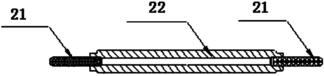
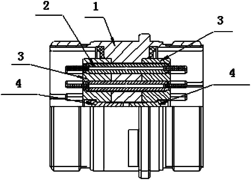
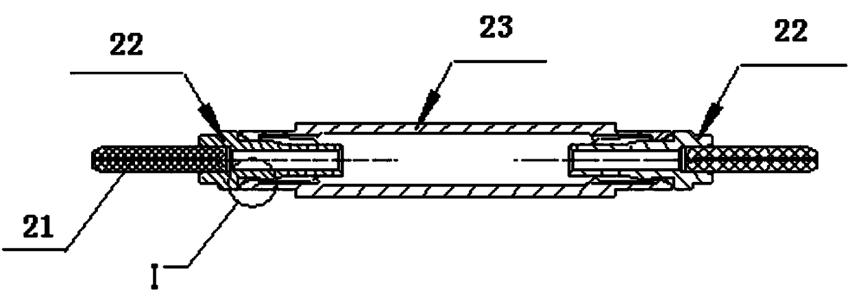
[0022] A floating optical fiber contact and its connector, including a housing 1, a floating optical fiber contact, a pressure plate 3 and a fastening screw 4, the floating optical fiber contact is located between the pressure plates at both ends inside the housing, and the pressure plate passes through the tight The solid screws are fixed on the housing to form a connector, and the ceramic pins are forcedly inserted into the flange to form a flange component. The flange component is assembled at both ends of the support sleeve to form a floating optical fiber contact. There are gaps in all directions between the support sleeves, which can move freely. There is a step hole in the position where the pressure plate is installed with the floating optical fiber contact piece. There is a step at the root of the spring claw of the support sleeve. A force relief structure is formed to ensure that the flange parts can float in the pressure plate.

[0023] The front part of the flange ...


PUM


Abstract

The invention provides a floating optical fiber contact member and a connector thereof, which comprises a housing, a floating optical fiber contact member, pressure plates and fastening screws. The floating optical fiber contact member is arranged between the pressure plates at the two ends in the housing; and the pressure plates are fixed to the housing through the fastening screws to form a connector. The floating optical fiber contact member is formed by ceramic pins, flange discs and a support sleeve. The ceramic pins are inserted into the flange discs to form flange components respectively. The flange components are assembled at the two ends of the support sleeve to form the floating optical fiber contact member. Gaps are formed between the flange components at the two ends and the support sleeve correspondingly, and thus free movement can be achieved. Each pressure plate is provided with a step hole in the place installing the floating optical fiber contact member. The root portion of each elastic claw of the support sleeve is provided with a step. When the floating optical fiber contact member is installed into the pressure plates, the steps at the root portions of the elastic claws of the support sleeve are cooperated with the step holes in the pressure plates to form a force discharge structure, so that it can be ensured that the flange components can float in the pressure plates.

Description

technical field [0001] The invention belongs to an optical fiber contact piece and a connector thereof, in particular to a floating optical fiber contact piece and a connector thereof. Background technique [0002] figure 1 , figure 2 It is a current non-floating fiber optic contact and connector, which includes a housing, a non-floating fiber optic contact (including ceramic pins, flanges), a pressure plate and fastening screws; this contact The ceramic pins at both ends of the component are forcibly installed on the flange to form a non-floating optical fiber contact. The optical fiber contact is located between the pressure plates at both ends inside the housing. The pressure plate is fixed on the housing by fastening screws to form a connector. The disadvantage of this contact is that the ceramic pins at both ends and the metal flange form a lever structure. When the two ends of the connector are connected to the plug, the plugs at both ends transmit the connection fo...

Claims


Application Information

Patent Timeline
IPC IPC(8): G02B6/38
CPCG02B6/3818G02B6/3825G02B6/3869
Inventor 丘威麟胡治国
Owner CHINA AVIATION OPTICAL-ELECTRICAL TECH CO LTD
Why Eureka
Try Eureka