Eureka AIR delivers breakthrough ideas for toughest innovation challenges, trusted by R&D personnel around the world.

connector device

A technology of connectors and mating connectors, which is applied in the direction of two-part connecting devices, parts of connecting devices, vehicle connectors, etc., and can solve problems such as no time interval

Active Publication Date: 2019-03-26
JAPAN AVIATION ELECTRONICS IND LTD
View PDF5 Cites 0 Cited by
  • Summary
  • Abstract
  • Description
  • Claims
  • Application Information

AI Technical Summary

Problems solved by technology

Therefore, in the connector device provided by Patent Document 1, there is almost no time interval between disconnection of the detection terminal and disconnection of the power supply terminal.

Method used


Image

  • connector device
  • connector device
  • connector device

Examples


no. 1 example

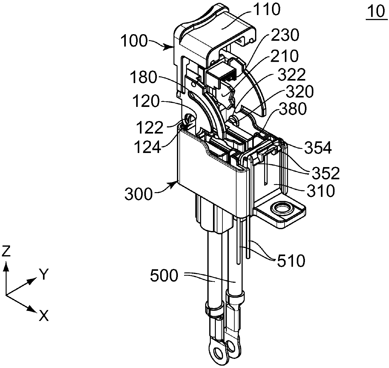
[0056] Such as figure 1 As shown, the connector device 10 according to the first embodiment of the present invention includes a connector 100 and a mating connector 300 . The mating connector 300 can be mated with the connector 100 . When the mating connector 300 is used, it is connected to an object such as an electric vehicle (not shown) and to a power system (not shown) and a motor (not shown). When the connector 100 is mated with the mating connector 300, the connector device 10 connects the power supply system to the motor, and supplies the electric current provided by the power supply system to the motor.

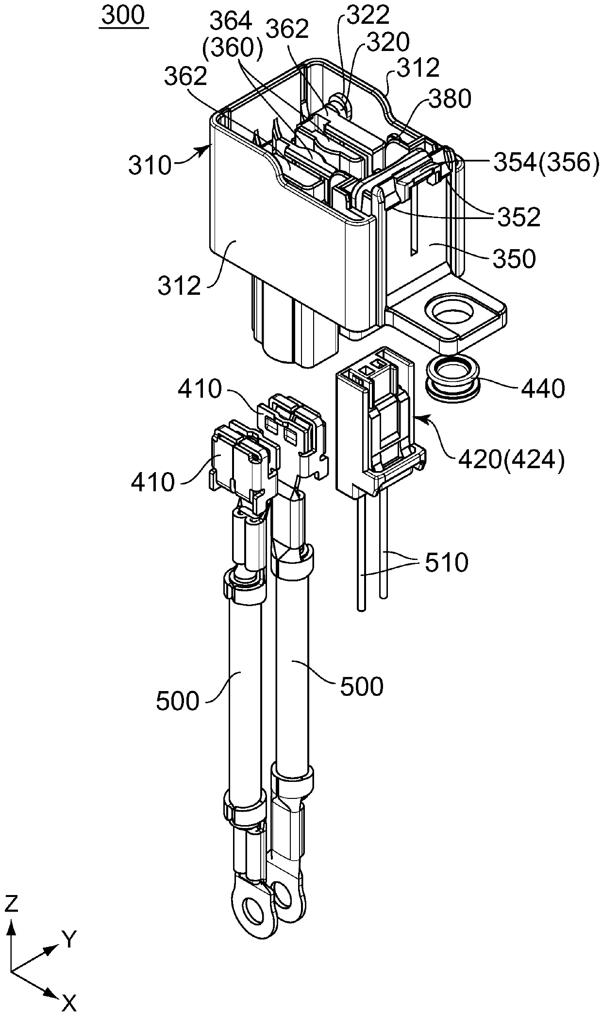
[0057] Such as image 3 As shown, the mating connector 300 includes a mating housing 310 , two mating power terminals 410 , a mating sub-connector 420 and an eyelet 440 .

[0058] refer to image 3 , the matching housing 310 includes two matching shaft parts 320 and two matching guide parts 380 . The engaging shaft portion 320 is a rotation shaft having an axis ...

no. 2 example

[0104] refer to Figures 36 to 40 , according to the second embodiment of the present invention, a connector device 10A includes a connector 100A and a mating connector 300A. The mating connector 300A is matable with the connector 100A. According to the connector device 10A of the second embodiment of the present invention, except for the guard portion 390A, other structures are the same as those described above. figure 1 The structure of the connector device 10 of the first shown embodiment is similar. therefore, Figures 36 to 40 Components shown that are the same as those of the first embodiment have the same reference numerals as the first embodiment. The direction definition in this embodiment is the same as that in the first embodiment.

[0105] Such as Figure 27 , 36 As shown in FIG. 40 , the mating connector 300A includes a mating housing 310A, two mating power supply terminals 410 (not shown), a mating sub-connector 420 and an aperture 440 . As for the mating...


PUM


Abstract

The invention provides a connector device, which includes a connector and a mating connector that can cooperate with the connector. The connector includes a housing, a power supply terminal and a detection terminal, and the mating connector includes a mating housing, a mating power supply terminal and a mating detection terminal. One of the housing and the mating housing is provided with a first release part, one of the housing and the mating housing is provided with a second releasing part, and one of the housing and the mating housing is provided with a protective part, and the connector can be connected with the mating The connector fits in any of the three states. When the connector is in the first state, in the operation direction, the protective part is located between the first release part and the second release part, which can prevent the second release part from operating after the first release part is operated. be operated accordingly. The invention can ensure that there is a sufficient time interval between the disconnection of the detection terminal and the coordination detection terminal, and the disconnection of the power supply terminal and the coordination power supply terminal.

Description

technical field [0001] The present invention relates to a connector device mounted on, for example, an electric vehicle or a hybrid vehicle for transmitting electric power from a power supply system. Background technique [0002] A connector device used to transmit power of a power supply system, which can be used to transmit a large current of about 100A. Therefore, it is necessary for such a connector device to include a mechanism for protecting the safety of personnel, and this type of connector device is disclosed in, for example, JPA 2002-343169 (Patent Document 1). [0003] Such as Figures 41A-41C As shown, the lever-mounted power circuit interrupting device 800 disclosed in Patent Document 1, or the connector device 800 , includes a connector 900 , a mating connector 950 and a lever 910 . Rod 910 is operably supported by connector 900 . The rod 910 is provided with a cam slot 912 and the mating connector 950 is provided with a cam pin 952 . The cam pin 952 is corr...

Claims


Application Information

Patent Timeline
Patent Type & Authority Patents(China)
IPC IPC(8): H01R13/629H01R13/502H01R24/00
CPCH01R13/502H01R13/62938H01R24/00H01R2201/26H01R13/7036Y02T10/70Y02T10/7072Y02T90/14H01R24/005B60L53/14H01R13/633H01R13/658B60Y2200/91B60Y2200/92Y02T90/12
Inventor 田端勇也
Owner JAPAN AVIATION ELECTRONICS IND LTD
Why Eureka
Eureka Blog
Learn More