Rotator cuff training device
A training device and rotator cuff technology, applied in passive exercise equipment, physical therapy and other directions, can solve the problems of small motor coil impedance, waste of electric energy, excessive movement, etc., to reduce the number of openings, avoid secondary trauma, and reduce additional consumption. Effect
- Summary
- Abstract
- Description
- Claims
- Application Information
AI Technical Summary
Problems solved by technology
Method used
Image
Examples
Embodiment 1
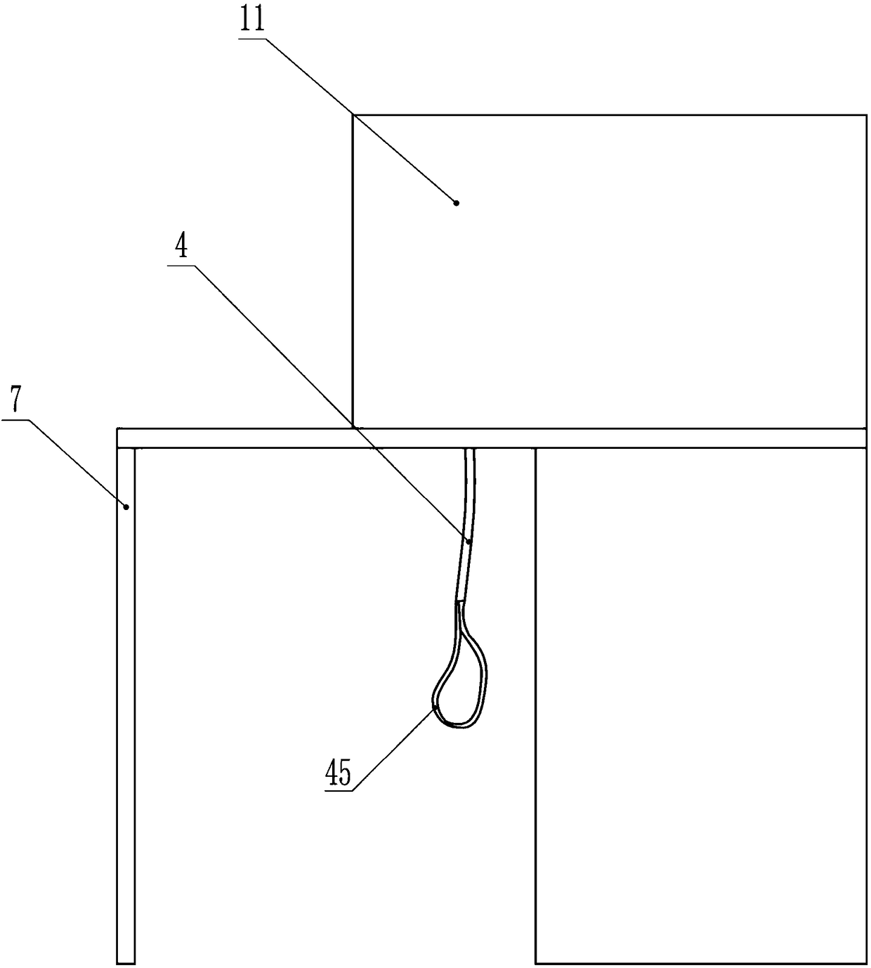
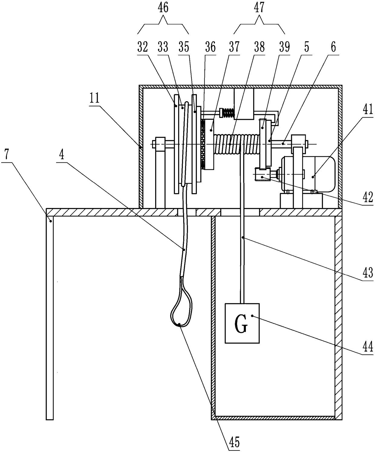
[0021] In Example 1, such as Figure 1 to 4 As shown, the present invention includes a frame body 7, a housing 11, a No. 1 reel 46, a No. 2 reel 47, a traction rope 4, a weight rope 43, a seat 13 and a motor 41. For ease of description, it is assumed that in this embodiment, the direction where the No. 1 reel 46 is located is forward, and the direction where the motor 41 is located is backward.
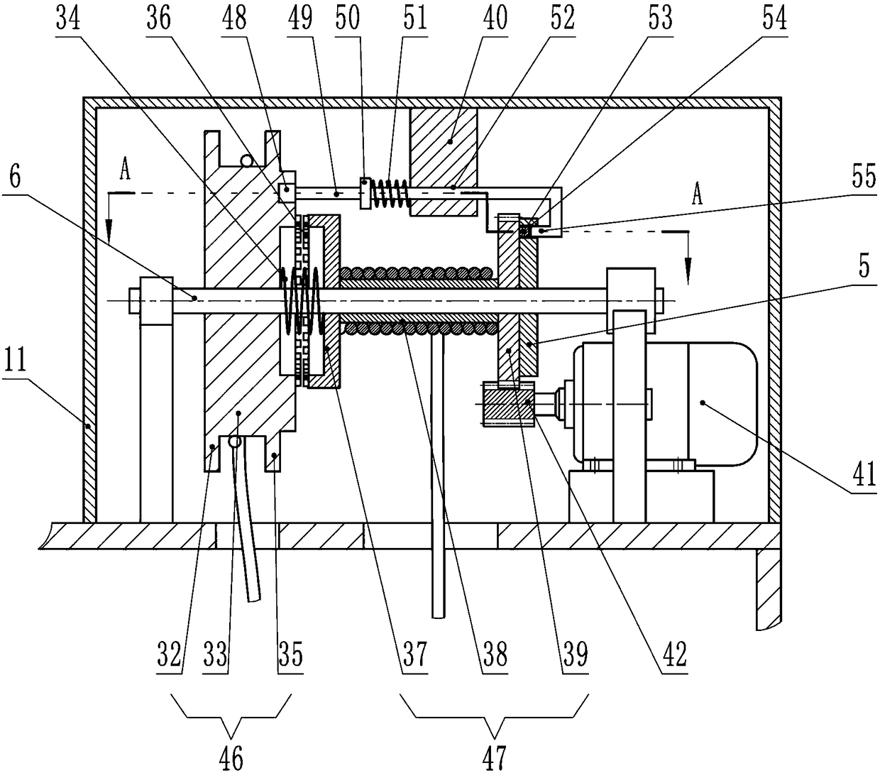
[0022] The No. 1 reel 46 and No. 2 reel 47 are respectively located in the upper shell 11 of the frame body 7 and respectively include a No. 1 cylinder body 33, a No. 2 cylinder body 38 and a No. 1 side plate 32 fixed at both ends of the No. 1 cylinder body 33. And the No. 2 side plate 35, the No. 3 side plate 37 and the No. 4 side plate 39 at both ends of the No. 2 cylinder body 38. The numbering sequence is set in the order from front to back. The order is the No. 1 to No. 4 side plates. The side plate 32, the second side plate 35, and the third side plate 37 are circular. The diamete...
Embodiment 2
[0033] Example 2 is more suitable for patients with frozen shoulder, who also have frozen shoulder joint adhesions. Patients with shoulder joint adhesions have very poor joint mobility. If the arm moves too fast, it may cause secondary damage to the stiff joints. For some patients, exercise equipment with speed-limiting devices should be used to help patients with rehabilitation training. In this embodiment, such as Figure 5 to 8 As shown, a gear box 58 is added on the basis of Embodiment 1. In the present invention, the gear box 58 can function as a speed limiter, so that the exercise equipment can run at a slower speed. In this embodiment, the technical features that have nothing to do with the gear box 58 are the same as those in Embodiment 1, and will not be repeated in this embodiment. Since the direction of movement obstacles for frozen shoulder is both forward and lateral extension, the seat 13 can be placed according to the patient’s specific rehabilitation requiremen...
Embodiment 3
[0041] In Embodiment 3, this embodiment is derived on the basis of Embodiment 2. The main structure of this embodiment is the same as that of Embodiment 2. The following only describes the different technical features between this embodiment and Embodiment 2. The same technical features will not be repeated.
[0042] Such as Picture 9 , 10 11, this embodiment also includes a chute rod 26, a sixth gear 28, a seventh gear 30 and a hand wheel 1.
[0043] The protruding end of the slider cylindrical structure 22 is hinged with one end of the connecting rod 25, and the other end of the connecting rod 25 is hinged with the sliding groove rod 26. The chute rod 26 is matedly connected with the rocker 29. The rocker 29 has teeth on one side to form a rack structure. On the rocker 29, on the side opposite to the teeth, there are two sides extending inward and outward. The protruding structure makes the rocker 29 form a T-shaped cross-section, and the sliding groove rod 26 is provided with ...
PUM
 Abstract
Description
Claims
Application Information
 - R&D
- Intellectual Property
- Life Sciences
- Materials
- Tech Scout
- Unparalleled Data Quality
- Higher Quality Content
- 60% Fewer Hallucinations
Browse by: Latest US Patents, China's latest patents, Technical Efficacy Thesaurus, Application Domain, Technology Topic, Popular Technical Reports.
© 2025 PatSnap. All rights reserved.Legal|Privacy policy|Modern Slavery Act Transparency Statement|Sitemap|About US| Contact US: help@patsnap.com


