High-efficiency mixing type crusher

A hybrid and crusher technology, applied in the field of mechanical equipment, can solve the problems of low crushing efficiency, large particle size, blockage, etc., and achieve the effect of simple structure, small particle diameter and small particles

Inactive Publication Date: 2018-05-29
CHENGDU TIAN HANG ZHI HONG IP MANAGEMENT CO LTD
View PDF0 Cites 1 Cited by
  • Summary
  • Abstract
  • Description
  • Claims
  • Application Information

AI Technical Summary

Problems solved by technology

[0002] Crusher is widely used in mining, smelting, building materials, roads, railways, water conservancy and chemical industries and many other sectors. When the drum is crushed, it often has faults such as cloggin

Method used


Image

  • High-efficiency mixing type crusher
  • High-efficiency mixing type crusher
  • High-efficiency mixing type crusher

Examples


Embodiment 1

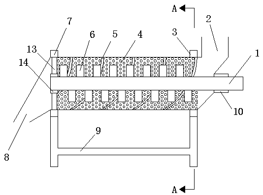
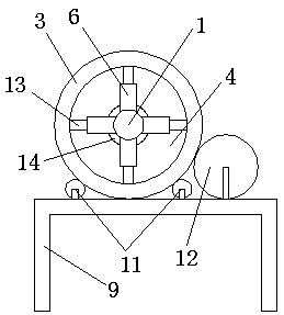
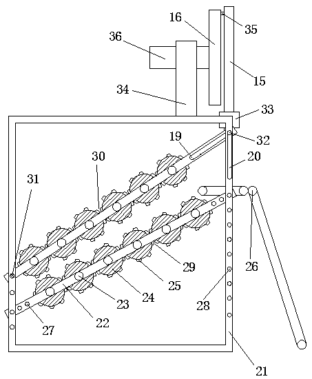
[0037] As a preferred embodiment of the present invention, with reference to the attached figure 1 , attached figure 2 And attached image 3 , this embodiment discloses a high-efficiency hybrid crusher, this embodiment includes:

[0038]A high-efficiency hybrid crusher, comprising a first crushing mechanism and a second crushing mechanism, the first crushing mechanism includes a bracket 21, a crushing roller group 29 is arranged on the bracket 21, and a crushing roller group 29 is arranged above the crushing roller group 29 Crushing roller group two 30, one end of crushing roller group two 30 is hinged to bracket one 21 through hinge point 31, and the other end reciprocates around hinge point 31; crushing roller group one 29 and crushing roller group two 30 are composed of multiple crushing rollers 24 Arranged side by side; crushing roller group 1 29 and crushing roller group 2 30 are arranged obliquely, the distance between crushing roller group 1 29 and crushing roller gr...

Embodiment 2

[0052] As a preferred embodiment of the present invention, with reference to the attached figure 1 , attached figure 2 And attached image 3 , this embodiment discloses a high-efficiency hybrid crusher, this embodiment includes:

[0053] A high-efficiency hybrid crusher, comprising a first crushing mechanism and a second crushing mechanism, the first crushing mechanism includes a bracket 21, a crushing roller group 29 is arranged on the bracket 21, and a crushing roller group 29 is arranged above the crushing roller group 29 Crushing roller group two 30, one end of crushing roller group two 30 is hinged to bracket one 21 through hinge point 31, and the other end reciprocates around hinge point 31; crushing roller group one 29 and crushing roller group two 30 are composed of multiple crushing rollers 24 Arranged side by side; crushing roller group 1 29 and crushing roller group 2 30 are arranged obliquely, the distance between crushing roller group 1 29 and crushing roller g...


PUM


Abstract

The invention relates to the technical field of mechanical equipment, and particularly relates to a high-efficiency mixing type crusher. The high-efficiency mixing type crusher comprises a first crushing mechanism and a second crushing mechanism; the first crushing mechanism comprises a first crushing roll set and a second crushing roll set; both the first crushing roll set and the second crushingroll set comprise fixed rods; crushing rolls are connected with the fixed rods; a second chute is formed on the second crushing roll set; a first chute is formed on a first bracket; a cross bar is connected in a sliding mode with the second chute and the first chute; a cam is formed at the top of the first bracket; a groove is formed in the cam; a vertical bar is arranged at the middle part of the cross bar; the vertical bar is provided with a sliding block; the second crushing mechanism comprises a roller; the roller is of a filter screen shape; a rotating shaft is arranged in the roller; crushing teeth are formed on the rotating shaft. According to the invention, big materials are subjected to primary crushing by the first crushing mechanism, and then the materials subjected to primarycrushing are placed into the second crushing mechanism to carry out secondary crushing so as to achieve a function of enabling crushed particles to be small in a case of efficiently crushing.

Description

technical field [0001] The invention relates to the technical field of mechanical equipment, in particular to a high-efficiency hybrid crusher. Background technique [0002] Crusher is widely used in mining, smelting, building materials, roads, railways, water conservancy and chemical industries and many other sectors. When the drum is crushed, it often has faults such as clogging and jamming. The crushing efficiency is not high, and the particle size of the crushed particles is large, and it cannot be maintained at a high efficiency at the same time. Contents of the invention [0003] The purpose of the present invention is to propose a high-efficiency hybrid crusher to solve the problems existing in the prior art, which can achieve small crushed particles under the condition of high-efficiency crushing. [0004] In order to achieve the above object, the technical scheme adopted in the present invention is: [0005] A high-efficiency hybrid crusher, comprising a first c...

Claims


Application Information

Patent Timeline
IPC IPC(8): B02C21/00B02C4/08B02C4/30B02C4/42B02C18/14B02C23/16
CPCB02C21/00B02C4/08B02C4/30B02C4/42B02C18/145B02C23/16B02C2023/165
Inventor 王红丽
Owner CHENGDU TIAN HANG ZHI HONG IP MANAGEMENT CO LTD
Why Eureka
Try Eureka