Concave die base plate for drop hammer die and application method
A technology of concave die backing plate and drop hammer die, which is used in metal processing equipment, forming tools, manufacturing tools, etc., can solve the problems of parts cracking, difficult material feeding, low qualification rate, etc., and achieves the reduction of tensile stress, Simple structure and high pass rate
- Summary
- Abstract
- Description
- Claims
- Application Information
AI Technical Summary
Problems solved by technology
Method used
Image

Examples
Embodiment 1
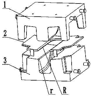
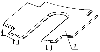
[0024] Embodiment 1: see figure 1 and figure 2 , a die backing plate 2 for the drop hammer die, which is arranged between the punch 1 and the die 3, and is used for processing the fairing parts with a deep depth, and the die 3 is provided with a depression for the punch 1 to embed , the radius r of the fillet on the upper edge of the depression includes a plate body, the plate body is matched with the upper surface of the die 3, and the plate body is provided with an opening corresponding to the depression of the die 3, and the shape of the opening is the same as The upper edge of the depression is straight, and the opening size is 1mm-2mm larger than the upper edge size of the die 3. The upper edge of the opening has a fillet radius R, and the fillet radius R>r. One side of the plate body is provided with a Its positioning block 4 on the die 3 .
[0025] In this embodiment: there are two limiting blocks 4, which are symmetrically distributed on one side of the plate body. ...
Embodiment 2
[0039] Assuming that the thickness t of the plate is 0.8mm, the fillet radius in the backing plate 2 of the die is R=12t=9.6mm, at this time the value of the fillet radius at the root of the flange of the fairing part is 6.5m, so we choose r to be 6.5m , after calculation, r=(0.6-0.8)R, then only one die backing plate 2 is selected;
Embodiment 3
[0041] If r=5mm at this time, then r<(0.6-0.8)R, then select multiple die backing plates 2 for transition, according to the formula
[0042] Formula R N =(0.6-0.8)R N-1
[0043] r=(0.6-0.8)R N ;
[0044] It can be seen that at least two die backing plates 2 need to be selected, namely R1 and R2,
[0045] R1=12t=9.6mm;
[0046] R2=(0.6-0.8)*R1=(5.76-7.86);
[0047] r=(0.6-0.8)*R2=5mm.
PUM
 Abstract
Description
Claims
Application Information
 - Generate Ideas
- Intellectual Property
- Life Sciences
- Materials
- Tech Scout
- Unparalleled Data Quality
- Higher Quality Content
- 60% Fewer Hallucinations
Browse by: Latest US Patents, China's latest patents, Technical Efficacy Thesaurus, Application Domain, Technology Topic, Popular Technical Reports.
© 2025 PatSnap. All rights reserved.Legal|Privacy policy|Modern Slavery Act Transparency Statement|Sitemap|About US| Contact US: help@patsnap.com